Nissan Sentra Service Manual: P1588 G Sensor
DTC Logic
DTC DETECTION LOGIC
|
DTC |
CONSULT screen terms (Trouble diagnosis content) |
DTC detection condition |
Possible causes |
| P1588 | G Sensor (Gravity Sensor Circuit) | When the following diagnosis conditions are
satisfied and the detection conditions are satisfied
twice in the same DC: Diagnosis condition (1 second or more)
Detection condition
|
G sensor |
NOTE:
DC stands for “DRIVING CYCLE” and indicates a series of driving cycle of “Ignition switch OFF → ON → driving → OFF”.
DTC CONFIRMATION PROCEDURE
CAUTION:
Be careful of the driving speed.
1.PREPARATION BEFORE WORK
If another “DTC CONFIRMATION PROCEDURE” occurs just before, turn ignition switch OFF and wait for at least 10 seconds, then perform the next test.
>> GO TO 2.
2.CHECK DTC DETECTION
 With CONSULT
- Start the engine.
- Select “Data Monitor” in “TRANSMISSION”.
- Select “G SPEED”.
- Drive the vehicle.
- Maintain the following conditions for 8 seconds or more.
Selector lever : “D” position
G SPEED : 0.05 G or more
- Stop the vehicle
CAUTION:
Never stop the engine.
- Repeat steps 4 through 6.
- Check the DTC.
Is “P1588” detected? YES >> Go to TM-221, "Diagnosis Procedure".
NO >> INSPECTION END
Diagnosis Procedure
1.CHECK G SENSOR SIGNAL
 With CONSULT
- Park the vehicle on a level surface.
- Turn ignition switch ON.
- Select “Data Monitor” in “TRANSMISSION”.
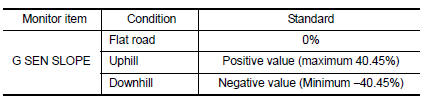
- Select “G SEN SLOPE”.
- Swing the vehicle and check if the value varies between −40.45% and 40.45%.
Is the inspection result normal? YES >> GO TO 2.
NO >> GO TO 3.
2.CALIBRATION OF G SENSOR (PART 1)
 With CONSULT
- Select “Self Diagnostic Results” in “TRANSMISSION”.
- Touch “Erase”.
>> Perform “CALIBRATION OF G SENSOR”. Refer to TM-147, "Work Procedure".
3.Check g sensor
- Remove G sensor. Refer to TM-265, "Removal and Installation".
- Connect the all connectors.
- Turn ignition switch ON
- Check voltage between TCM connector terminal and ground.
 : Direction of gravitational
force
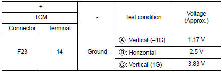
Is the inspection result normal? YES >> GO TO 4.
NO >> Replace G sensor. Refer to TM-265, "Removal and Installation".
4.CALIBRATION OF G SENSOR (PART 2)
 With CONSULT
- Install G sensor. Refer to TM-265, "Removal and Installation".
- Select “Self Diagnostic Results” in “TRANSMISSION”.
- Touch “Erase”.
>> Perform “CALIBRATION OF G SENSOR”. Refer to TM-147, "Work Procedure".
 P1586 G Sensor
DTC Logic
DTC DETECTION LOGIC
DTC
CONSULT screen terms
(Trouble diagnosis content)
DTC detection condition
Possible causes
P1586
G Sensor
(Gravity Sensor Circuit)
...
 P2765 Input speed sensor B
DTC Logic
DTC DETECTION LOGIC
DTC
CONSULT screen terms
(Trouble diagnosis content)
DTC detection condition
Possible causes
P2765
INPUT SPEED SENSOR B
(Input/Turbine ...
Other materials:
Wiring diagram
Navigation without bose
Wiring diagram
...
Wind deflector
Exploded view
Spring
Wind deflector
Roof panel
Sunshade
Glass lid
Front
Removal and installation
REMOVAL
Open the glass lid.
Release the springs (LH/RH), then remove the wind deflector.
INSTALLATION
Installation is in the reverse order of removal. ...
Environmental factors influence the rate of corrosion
Moisture
Accumulation of sand, dirt and water on the vehicle
body underside can accelerate corrosion.
Wet floor coverings will not dry completely inside
the vehicle and should be removed for drying to
avoid floor panel corrosion.
Relative humidity
Corrosion will be accelerated in areas of h ...
