Nissan Sentra Service Manual: Electrical load signal
Description
The electrical load signal (Headlamp switch signal, rear window defogger switch signal, etc.) is transferred via the CAN communication line.
Component Function Check
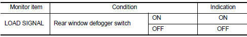
1.CHECK REAR WINDOW DEFOGGER SWITCH FUNCTION
 With CONSULT
- Turn ignition switch ON.
- Select “DATA MONITOR” mode of “ENGINE” using CONSULT.
- Select “LOAD SIGNAL” and check indication as per the following conditions.
Is the inspection result normal? YES >> GO TO 2.
NO >> Proceed to EC-461, "Diagnosis Procedure".
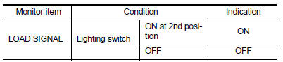
2.CHECK LIGHTING SWITCH FUNCTION
 With CONSULT
Check “LOAD SIGNAL” indication as per the following conditions.
Is the inspection result normal? YES >> GO TO 3.
NO >> Proceed to EC-461, "Diagnosis Procedure".
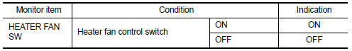
3.CHECK HEATER FAN CONTROL SWITCH FUNCTION
 With CONSULT
Select “HEATER FAN SW” and check indication as per the following conditions.
Is the inspection result normal? YES >> INSPECTION END
NO >> Proceed to EC-461, "Diagnosis Procedure".
Diagnosis Procedure
1.INSPECTION START
Confirm the malfunctioning circuit (rear window defogger, headlamp or heater fan). Refer to EC-461, "Component Function Check".
Which circuit is related to the incident? Rear window defogger>>GO TO 2.
Headlamp>>GO TO 3.
Heater fan>>GO TO 4.
2.CHECK REAR WINDOW DEFOGGER SYSTEM
Check the rear window defogger system. Refer to DEF-27, "Work Flow".
>> INSPECTION END
3.CHECK HEADLAMP SYSTEM
Check the headlamp system. Refer to EXL-85, "Work Flow".
>> INSPECTION END
4.CHECK HEATER FAN CONTROL SYSTEM
Check the heater fan control system. Refer to HA-15, "Workflow".
>> INSPECTION END
 Ignition signal
Component Function Check
1.INSPECTION START
Turn ignition switch OFF.
Start engine.
Does the engine start?
YES >> GO TO 2.
NO >> Proceed to EC-456, "Diagnosis Procedure& ...
 Cooling fan
Component Function Check
1.CHECK COOLING FAN FUNCTION
With CONSULT
Turn ignition switch ON.
Perform “FAN” in “ACTIVE TEST” mode of “ENGINE” using CONSULT
Check ...
Other materials:
Ecu diagnosis information
Av control unit
Reference value
TERMINAL LAYOUT
PHYSICAL VALUES
Dtc index
Bose speaker amp
Reference value
TERMINAL LAYOUT
PHYSICAL VALUES
...
Diagnosis description : system readiness
test (SRT) code
System Readiness Test (SRT) code is specified in Service $01 of SAE J1979/ISO
15031-5.
As part of an enhanced emissions test for Inspection & Maintenance (I/M),
certain states require the status of
SRT be used to indicate whether the ECM has completed self-diagnosis of major
emission s ...
Precaution
Precaution for supplemental restraint system (srs)
"air bag" and "seat belt pre-tensioner"
The Supplemental Restraint System such as “AIR BAG” and “SEAT BELT
PRE-TENSIONER”, used along
with a front seat belt, helps to reduce the risk or severity of injur ...
