Nissan Sentra Service Manual: ECU diagnosis information
A/C AUTO AMP
Reference Value
TERMINAL LAYOUT

PHYSICAL VALUES
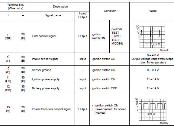
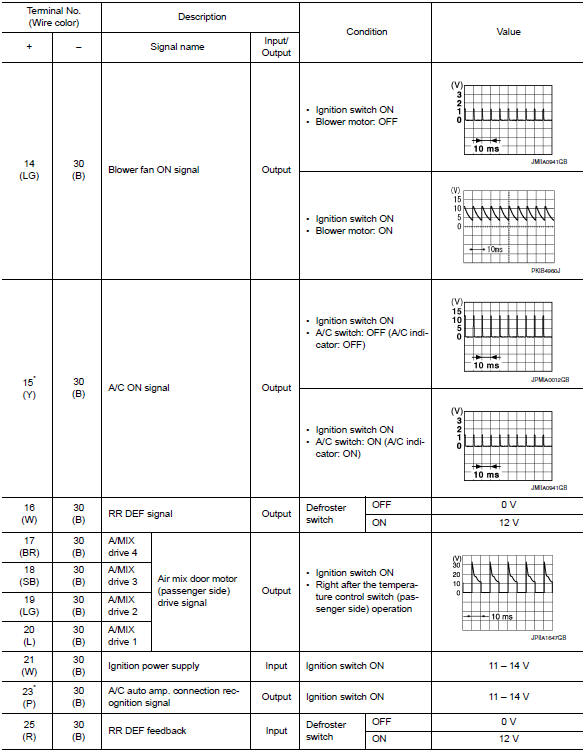
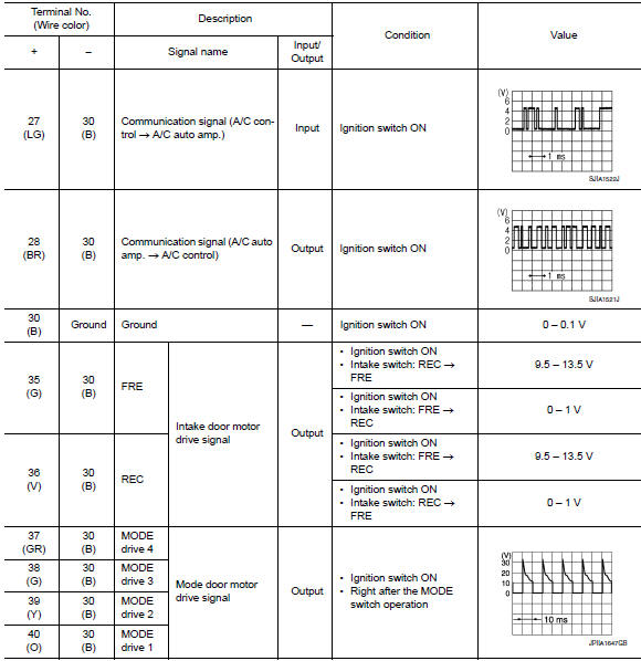
*:With manual A/C
ECM, IPDM E/R, BCM
List of ECU Reference

 System description
COMPONENT PARTS
Component Part Location
ECM
IPDM E/R
BCM (view with combination meter
removed)
A/C auto amp. (view with A/C switch
assembly removed)
A/C switch assembly
A/C ...
 Wiring diagram
Manual air conditioning system
Wiring Diagram
Manual heater system
Wiring Diagram
...
Other materials:
Push-Button Ignition Switch (if so equipped)
WARNINGDo not operate the push-button ignition
switch while driving the vehicle except in
an emergency. (The engine will stop when
the ignition switch is pushed 3 consecutive
times in quick succession or the ignition
switch is pushed and held for more
than 2 seconds.) If ...
P0744 Torque converter
DTC Logic
DTC DETECTION LOGIC
DTC
CONSULT screen terms
(Trouble diagnosis content)
DTC detection condition
Possible causes
P0744
TORQUE CONVERTER
(Torque converter clutch circuit
intermittent)
The torque converter slip speed is at or above
a set value (40 ...
Basic inspection
Diagnosis and repair work flow
Work flow
OVERALL SEQUENCE
DETAILED FLOW
1.GET INFORMATION FOR SYMPTOM
Get detailed information from the customer about the symptom (the
condition and the environment when
the incident/malfunction occurs).
Check operation condition of the function th ...
