Nissan Sentra Service Manual: Ecm branch line circuit
Diagnosis Procedure
1.Check connector
- Turn the ignition switch off.
- Disconnect the battery cable from the negative terminal.
- Check the terminals and connectors of the ECM for damage, bend and loose connection (unit side and connector side).
Is the inspection result normal? YES >> GO TO 2.
NO >> Repair the terminal and connector.
2.Check harness for open circuit
- Disconnect the connector of ECM.
- Check the resistance between the ecm harness connector terminals.
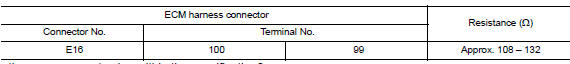
Is the measurement value within the specification? Yes >> go to 3.
No >> repair the ecm branch line.
3.Check power supply and ground circuit
Check the power supply and the ground circuit of the ecm. Refer to ec-164, "diagnosis procedure".
Is the inspection result normal? Yes (present error)>>replace the ecm. Refer to ec-485, "removal and installation".
Yes (past error)>>error was detected in the ecm branch line.
No >> repair the power supply and the ground circuit.
 Main line between dlc and hvac circuit
Diagnosis Procedure
1.Check harness continuity (open circuit)
Turn the ignition switch OFF.
Disconnect the battery cable from the negative terminal.
Disconnect the following harness connector ...
 Abs branch line circuit
Diagnosis procedure
1.CHECK CONNECTOR
Turn the ignition switch OFF.
Disconnect the battery cable from the negative terminal.
Check the terminals and connectors of the ABS actuator and electri ...
Other materials:
Parts Requiring Angle Tightening
Use the Tool for the final tightening of the following engine parts:
Tool number : KV10112100 (BT-8653-A)
Camshaft sprocket (INT) bolt
Cylinder head bolts
Main bearing cap bolts
Connecting rod cap bolts
Crankshaft pulley bolt (No the angle wrench is required as bolt flange
is pr ...
Precaution for work
When removing or disassembling each component, be careful not to damage
or deform it. If a component
may be subject to interference, be sure to protect it with a shop cloth.
When removing (disengaging) components with a screwdriver or similar
tool, be sure to wrap the component
with a ...
Rear shock absorber
Exploded View
Rear suspension beam
Shock absorber
Bound bumper
Bound bumper cover
Washer
Bushing
Distance tube
Bushing
Washer
Piston rod lock nut
Cap
Front
Removal and Installation
REMOVAL
Remove the rear shock tower access flap.
Remove the cap from the rear s ...
