Nissan Sentra Service Manual: Dtc/circuit diagnosis
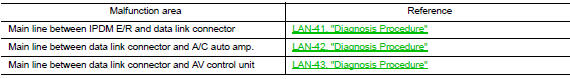
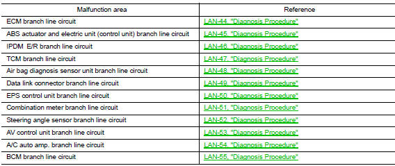
Malfunction area chart
Main line
Branch line
Short circuit

Main line between ipdm-e and dlc circuit
Diagnosis procedure
1.Check connector
- Turn the ignition switch off.
- Disconnect the battery cable from the negative terminal.
- Check the following terminals and connectors for damage, bend and loose connection (connector side and harness side).
- Harness connector E4
- Harness connector m2
Is the inspection result normal? Yes >> go to 2.
No >> repair the terminal and connector.
2.Check harness continuity (open circuit)
- Disconnect the following harness connectors.
- IPDM E/R
- Harness connectors e4 and m2
- Check the continuity between the ipdm e/r harness connector and the harness connector.
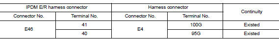
Is the inspection result normal? Yes >> go to 3.
No >> repair the main line between the ipdm e/r and the harness connector e4.
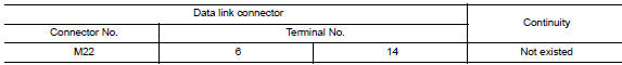
3.Check harness continuity (open circuit)
Check the continuity between the harness connector and the data link connector.
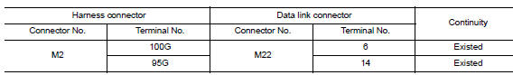
Is the inspection result normal? YES (Present error)>>Check CAN system type decision again.
YES (Past error)>>Error was detected in the main line between the IPDM E/R and the data link connector.
NO >> Repair the main line between the harness connector M2 and the data link connector.
Main line between dlc and hvac circuit
Diagnosis procedure
1.Check harness continuity (open circuit)
- Turn the ignition switch OFF.
- Disconnect the battery cable from the negative terminal.
- Disconnect the following harness connectors.
- ECM
- A/c auto amp
- Check the continuity between the data link connector and the a/c auto amp. Harness connector.
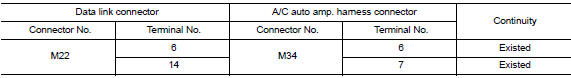
Is the inspection result normal? Yes (present error)>>check can system type decision again.
Yes (past error)>>error was detected in the main line between the data link connector and the a/c auto amp.
No >> repair the main line between the data link connector and the a/c auto amp.
Main line between dlc and av circuit
Diagnosis procedure
1.Check harness continuity (open circuit)
- Turn the ignition switch off.
- Disconnect the battery cable from the negative terminal.
- Disconnect the following harness connectors.
- Ecm
- Av control unit
- Check the continuity between the data link connector and the av control unit harness connector.
- With navigation system and BOSE audio system
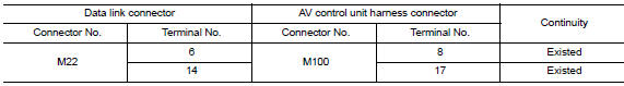
- With navigation system without bose audio system
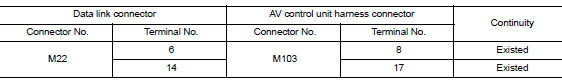
Is the inspection result normal? YES (Present error)>>Check CAN system type decision again.
YES (Past error)>>Error was detected in the main line between the data link connector and the AV control unit .
NO >> Repair the main line between the data link connector and the AV control unit.
Ecm branch line circuit
Diagnosis Procedure
1.Check connector
- Turn the ignition switch off.
- Disconnect the battery cable from the negative terminal.
- Check the terminals and connectors of the ECM for damage, bend and loose connection (unit side and connector side).
Is the inspection result normal? Yes >> go to 2.
No >> repair the terminal and connector.
2.Check harness for open circuit
- Disconnect the connector of ecm
- Check the resistance between the ecm harness connector terminals.
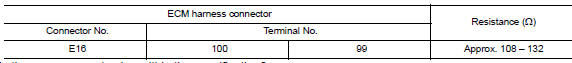
Is the measurement value within the specification? YES >> GO TO 3.
NO >> Repair the ECM branch line.
3.Check power supply and ground circuit
Check the power supply and the ground circuit of the ecm. Refer to ec-164, "diagnosis procedure".
Is the inspection result normal? Yes (present error)>>replace the ecm. Refer to ec-485, "removal and installation".
Yes (past error)>>error was detected in the ecm branch line.
No >> repair the power supply and the ground circuit.
Abs branch line circuit
Diagnosis Procedure
1.Check connector
- Turn the ignition switch off.
- Disconnect the battery cable from the negative terminal.
- Check the terminals and connectors of the abs actuator and electric unit (control unit) for damage, bend and loose connection (unit side and connector side).
Is the inspection result normal? Yes >> go to 2.
No >> repair the terminal and connector.
2.Check harness for open circuit
- Disconnect the connector of abs actuator and electric unit (control unit).
- Check the resistance between the abs actuator and electric unit (control unit) harness connector terminals.
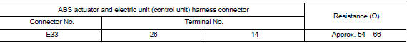
Is the measurement value within the specification? Yes >> go to 3.
No >> repair the abs actuator and electric unit (control unit) branch line.
3.Check power supply and ground circuit
Check the power supply and the ground circuit of the abs actuator and electric unit (control unit). Refer to brc-62, "diagnosis procedure".
Is the inspection result normal? Yes (present error)>>replace the abs actuator and electric unit (control unit). Refer to brc-110, "removal and installation".
Yes (past error)>>error was detected in the abs actuator and electric unit (control unit) branch line.
No >> repair the power supply and the ground circuit.
Ipdm-e branch line circuit
Diagnosis Procedure
1.Check connector
- Turn the ignition switch off.
- Disconnect the battery cable from the negative terminal.
- Check the terminals and connectors of the ipdm e/r for damage, bend and loose connection (unit side and connector side).
Is the inspection result normal? YES >> GO TO 2.
NO >> Repair the terminal and connector.
2.Check harness for open circuit
- Disconnect the connector of ipdm e/r.
- Check the resistance between the IPDM E/R harness connector terminals.
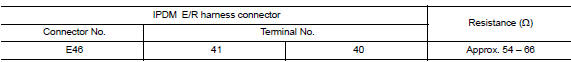
Is the measurement value within the specification? YES >> GO TO 3.
NO >> Repair the IPDM E/R branch line.
3.Check power supply and ground circuit
Check the power supply and the ground circuit of the ipdm e/r. Refer to the following.
- With intelligent key system: refer to bcs-67, "diagnosis procedure".
- Without intelligent key system: refer to bcs-120, "diagnosis procedure".
Is the inspection result normal? Yes (present error)>>replace the ipdm e/r. Refer to the following.
- With intelligent key system: refer to bcs-73, "removal and installation".
- Without intelligent key system: refer to bcs-126, "removal and installation".
Yes (past error)>>error was detected in the ipdm e/r branch line.
No >> repair the power supply and the ground circuit.
Tcm branch line circuit
Diagnosis procedure
1.Check connector
- Turn the ignition switch off.
- Disconnect the battery cable from the negative terminal.
- Check the following terminals and connectors for damage, bend and loose connection (unit side and connector side).
- Tcm
- Harness connector f50
- Harness connector E64
Is the inspection result normal? Yes >> go to 2.
No >> repair the terminal and connector.
2.Check harness for open circuit
- Disconnect the connector of tcm.
- Check the resistance between the tcm harness connector terminals.
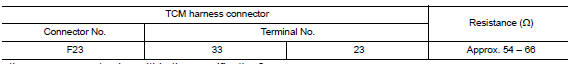
Is the measurement value within the specification? Yes >> go to 3.
No >> repair the tcm branch line.
3.Check power supply and ground circuit
Check the power supply and the ground circuit of the TCM. Refer to TM-234, "Diagnosis Procedure".
Is the inspection result normal? YES (Present error)>>Replace the TCM. Refer to the TM-263, "Removal and Installation".
YES (Past error)>>Error was detected in the TCM branch line.
NO >> Repair the power supply and the ground circuit.
A-bag branch line circuit
Diagnosis procedure
Warning:
Always observe the following items for preventing accidental activation.
- Before servicing, turn ignition switch off, disconnect battery negative terminal, and wait 3 minutes or more. (To discharge backup capacitor.)
- Never use unspecified tester or other measuring device.
1.Check connector
- Turn the ignition switch off
- Disconnect the battery cable from the negative terminal.
- Check the terminals and connectors of the air bag diagnosis sensor unit for damage, bend and loose connection (unit side and connector side).
Is the inspection result normal? Yes >> go to 2.
No >> replace the main harness.
2.Check air bag diagnosis sensor unit
Check the air bag diagnosis sensor unit. Refer to src-38, "work flow".
Is the inspection result normal? Yes >> replace the main harness.
No >> replace parts whose air bag system has a malfunction.
Dlc branch line circuit
Diagnosis Procedure
1.Check connector
- Turn the ignition switch off.
- Disconnect the battery cable from the negative terminal.
- Check the terminals and connectors of the data link connector for damage, bend and loose connection (connector side and harness side).
Is the inspection result normal? Yes >> go to 2.
No >> repair the terminal and connector.
2.Check harness for open circuit
Check the resistance between the data link connector terminals.
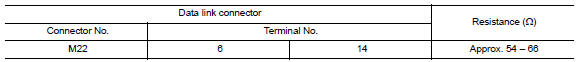
Is the measurement value within the specification? YES (Present error)>>Check CAN system type decision again.
YES (Past error)>>Error was detected in the data link connector branch line circuit.
NO >> Repair the data link connector branch line.
Eps branch line circuit
Diagnosis procedure
1.Check connector
- Turn the ignition switch off.
- Disconnect the battery cable from the negative terminal.
- Check the terminals and connectors of the eps control unit for damage, bend and loose connection (unit side and connector side).
Is the inspection result normal? Yes >> go to 2.
No >> repair the terminal and connector.
2.Check harness for open circuit
- Disconnect the connector of EPS control unit.
- Check the resistance between the eps control unit harness connector terminals.
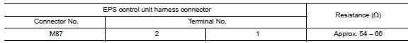
Is the measurement value within the specification? Yes >> go to 3.
No >> repair the eps control unit branch line.
3.Check power supply and ground circuit
Check the power supply and the ground circuit of the EPS control unit. Refer to STC-22, "Diagnosis Procedure".
Is the inspection result normal? YES (Present error)>>Replace the EPS control unit. Refer to STC-39, "Removal and Installation".
YES (Past error)>>Error was detected in the EPS control unit branch line.
NO >> Repair the power supply and the ground circuit.
M&A branch line circuit
Diagnosis procedure
1.Check connector
- Turn the ignition switch OFF.
- Disconnect the battery cable from the negative terminal.
- Check the terminals and connectors of the combination meter for damage, bend and loose connection (unit side and connector side).
Is the inspection result normal? Yes >> go to 2.
No >> repair the terminal and connector.
2.Check harness for open circuit
- Disconnect the connector of combination meter.
- Check the resistance between the combination meter harness connector terminals.
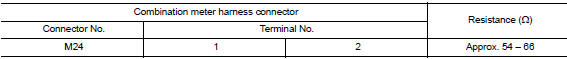
Is the measurement value within the specification? YES >> GO TO 3.
NO >> Repair the combination meter branch line.
3.Check power supply and ground circuit
Check the power supply and the ground circuit of the combination meter. Refer to mwi-52, "combination meter : diagnosis procedure".
Is the inspection result normal? Yes (present error)>>replace the combination meter. Refer to mwi-77, "removal and installation".
Yes (past error)>>error was detected in the combination meter branch line.
No >> repair the power supply and the ground circuit.
Strg branch line circuit
Diagnosis procedure
1.Check connector
- Turn the ignition switch off.
- Disconnect the battery cable from the negative terminal.
- Check the terminals and connectors of the steering angle sensor for damage, bend and loose connection (unit side and connector side).
Is the inspection result normal? Yes >> go to 2.
No >> repair the terminal and connector.
2.Check harness for open circuit
- Disconnect the connector of steering angle sensor.
- Check the resistance between the steering angle sensor harness connector terminals.
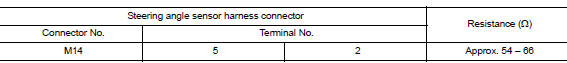
Is the measurement value within the specification? Yes >> go to 3.
No >> repair the steering angle sensor branch line.
3.Check power supply and ground circuit
Check the power supply and the ground circuit of the steering angle sensor. Refer to BRC-44, "Wiring Diagram".
Is the inspection result normal? YES (Present error)>>Replace the steering angle sensor. Refer to BRC-113, "Removal and Installation".
YES (Past error)>>Error was detected in the steering angle sensor branch line.
NO >> Repair the power supply and the ground circuit.
Av branch line circuit
Diagnosis procedure
1.Check connector
- Turn the ignition switch OFF.
- Disconnect the battery cable from the negative terminal.
- Check the terminals and connectors of the av control unit for damage, bend and loose connection (unit side and connector side).
Is the inspection result normal? YES >> GO TO 2.
NO >> Repair the terminal and connector.
2.Check harness for open circuit
- Disconnect the connector of av control unit.
- Check the resistance between the av control unit harness connector terminals.
- With navigation system without BOSE audio system
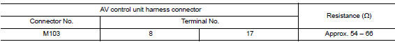
- With navigation system and bose audio system
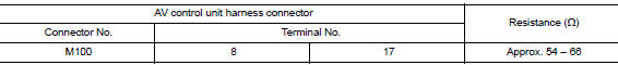
Is the measurement value within the specification? Yes >> go to 3.
No >> repair the av control unit branch line.
3.Check power supply and ground circuit
Check the power supply and the ground circuit of the av control unit. Refer to the following.
- With navigation system without bose audio system: refer to av-270, "av control unit : diagnosis procedure".
- With navigation system and bose audio system: refer to av-370, "av control unit : diagnosis procedure".
Is the inspection result normal? Yes (present error)>>replace the av control unit. Refer to the following.
- With navigation system without bose audio system: refer to av-298, "removal and installation".
- With navigation system and bose audio system: refer to av-406, "removal and installation".
Yes (past error)>>error was detected in the av control unit branch line.
No >> repair the power supply and the ground circuit.
Hvac branch line circuit
Diagnosis procedure
1.Check connector
- Turn the ignition switch OFF.
- Disconnect the battery cable from the negative terminal.
- Check the terminals and connectors of the a/c auto amp. For damage, bend and loose connection (unit side and connector side).
Is the inspection result normal? Yes >> go to 2.
No >> repair the terminal and connector.
2.Check harness for open circuit
- Disconnect the connector of a/c auto amp.
- Check the resistance between the a/c auto amp. Harness connector terminals.
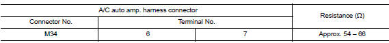
Is the measurement value within the specification? YES >> GO TO 3.
NO >> Repair the A/C auto amp. branch line.
3.Check power supply and ground circuit
Check the power supply and the ground circuit of the a/c auto amp. Refer to hac-83, "a/c auto amp. : Diagnosis procedure".
Is the inspection result normal? Yes (present error)>>replace the a/c auto amp. Refer to hac-105, "removal and installation".
Yes (past error)>>error was detected in the a/c auto amp. Branch line.
No >> repair the power supply and the ground circuit.
Bcm branch line circuit
Diagnosis procedure
1.Check connector
- Turn the ignition switch off.
- Disconnect the battery cable from the negative terminal.
- Check the terminals and connectors of the bcm for damage, bend and loose connection (unit side and connector side).
Is the inspection result normal? Yes >> go to 2.
No >> repair the terminal and connector.
2.Check harness for open circuit
- Disconnect the connector of bcm.
- Check the resistance between the BCM harness connector terminals.
- Without intelligent key system
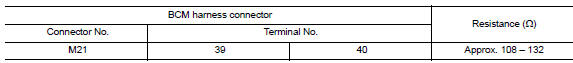
- With intelligent key system
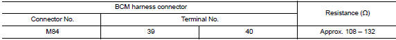
Is the measurement value within the specification? Yes >> go to 3.
No >> repair the bcm branch line.
3.Check power supply and ground circuit
Check the power supply and the ground circuit of the bcm. Refer to the following.
- With intelligent key system: refer to bcs-67, "diagnosis procedure".
- Without intelligent key system: refer to bcs-120, "diagnosis procedure".
Is the inspection result normal? YES (Present error)>>Replace the BCM. Refer to the following.
- With intelligent key system: refer to bcs-73, "removal and installation".
- Without intelligent key system: refer to bcs-126, "removal and installation".
YES (Past error)>>Error was detected in the BCM branch line.
NO >> Repair the power supply and the ground circuit.
Can communication circuit
Diagnosis procedure
1.Connector inspection
- Turn the ignition switch OFF.
- Disconnect the battery cable from the negative terminal.
- Disconnect all the unit connectors on can communication system.
- Check terminals and connectors for damage, bend and loose connection.
Is the inspection result normal? Yes >> go to 2.
No >> repair the terminal and connector.
2.Check harness continuity (short circuit)
Check the continuity between the data link connector terminals.
Is the inspection result normal? Yes >> go to 3.
No >> check the harness and repair the root cause.
3.Check harness continuity (short circuit)
Check the continuity between the data link connector and the ground.
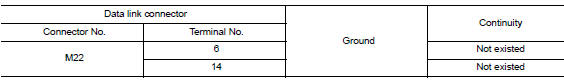
Is the inspection result normal? YES >> GO TO 4.
NO >> Check the harness and repair the root cause.
4.Check ecm and bcm termination circuit
- Remove the ecm and the bcm.
- Check the resistance between the ECM terminals.
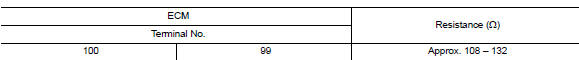
- Check the resistance between the bcm terminals.
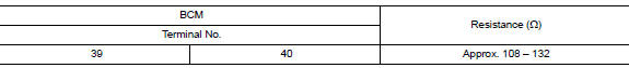
Is the measurement value within the specification? Yes >> go to 5.
No >> replace the ecm and/or the bcm.
5.Check symptom
Connect all the connectors. Check if the symptoms described in the “symptom (results from interview with customer)” are reproduced.
Inspection result reproduced>>go to 6.
Non-reproduced>>start the diagnosis again. Follow the trouble diagnosis procedure when past error is detected.
6.Check unit reproduction
Perform the reproduction test as per the following procedure for each unit.
- Turn the ignition switch off.
- Disconnect the battery cable from the negative terminal.
- Disconnect one of the unit connectors of can communication system.
Note:
Ecm and bcm have a termination circuit. Check other units first.
- Connect the battery cable to the negative terminal. Check if the symptoms described in the “symptom (results from interview with customer)” are reproduced.
Note:
Although unit-related error symptoms occur, do not confuse them with other symptoms.
Inspection result
Reproduced>>Connect the connector. Check other units as per the above procedure.
Non-reproduced>>Replace the unit whose connector was disconnected.
 Basic inspection
Diagnosis and repair workflow
Interview sheet
Note:
Refer to LAN-16, "Trouble Diagnosis Procedure" for how to use interview
sheet.
...
 Can system (type 1)
Dtc/circuit diagnosis ...
Other materials:
B1431, B1433 Seat belt pre-tensioner RH
Description
DTC B1431, B1433 SEAT BELT PRE-TENSIONER RH
The seat belt pre-tensioner RH is wired to the air bag diagnosis sensor unit.
The air bag diagnosis sensor unit
will monitor for opens and shorts in detected lines to the seat belt pre-tensioner
RH.
PART LOCATION
Refer to SRC-5, " ...
P0300, P0301, P0302, P0303, P0304 Misfire
DTC Logic
DTC DETECTION LOGIC
When a misfire occurs, engine speed will fluctuate. If the engine speed
fluctuates enough to cause the crankshaft
position (CKP) sensor (POS) signal to vary, ECM can determine that a misfire is
occurring.
Sensor
Input signal to ECM
ECM function
...
Precaution
Precaution for supplemental restraint system (srs) "air bag" and "seat
belt pre-tensioner"
The Supplemental Restraint System such as “AIR BAG” and “SEAT BELT PRE-TENSIONER”,
used along
with a front seat belt, helps to reduce the risk or severity of injur ...
