Nissan Sentra Service Manual: Basic inspection
Diagnosis and repair workflow
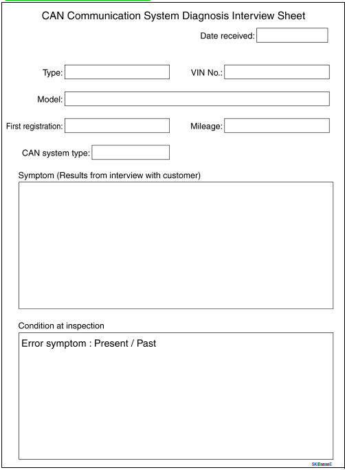
Interview sheet
Note:
Refer to LAN-16, "Trouble Diagnosis Procedure" for how to use interview sheet.

 Wiring diagram
Can system
Wiring Diagram
...
 Dtc/circuit diagnosis
Malfunction area chart
Main line
Branch line
Short circuit
Main line between ipdm-e and dlc circuit
Diagnosis procedure
1.Check connector
Turn the ignition switch off.
Discon ...
Other materials:
Precaution
Precaution for supplemental restraint system (srs) "air bag" and "seat
belt
pre-tensioner"
The supplemental restraint system such as “air bag” and “seat belt pre-tensioner”,
used along
with a front seat belt, helps to reduce the risk or severity of inju ...
C1105, C1106, C1107, C1108 Wheel sensor
Description
When the sensor rotor rotates, the magnetic field changes. It
converts the magnetic field changes to current
signals (rectangular wave) and transmits them to the ABS actuator and electric
unit (control unit).
DTC Logic
DTC DETECTION LOGIC
DTC
Display Item
Malfunct ...
Water outlet
Exploded View
CVT MODELS
Water control valve
Rubber ring
Radiator hose (upper)
Clamp
Water outlet
CVT oil warmer hose (outlet)
Heater hose (inlet)
Heater hose (outlet)
Electric throttle control actuator hose
(outlet)
Electric throttle control actuator hose
(inlet)
E ...
