Nissan Sentra Service Manual: Dtc/circuit diagnosis
U1000 can comm
Description
Refer to LAN-7, "CAN COMMUNICATION SYSTEM : System Description".
Dtc logic
Dtc detection logic
Note:
U1000 can be set if a module harness was disconnected and reconnected, perhaps during a repair. Confirm that there are actual can diagnostic symptoms and a present dtc by performing the self diagnostic result procedure.
| Consult display | Dtc detection condition | Possible cause |
| Can comm circuit [u1000] | When any listed module cannot communicate with can communication signal continuously for 2 seconds or more with ignition switch on | In CAN communication system, any item (or
items) of the following listed below is malfunctioning.
|
Diagnosis procedure
1. Perform self diagnostic result
- Turn ignition switch ON and wait for 2 second or more.
- Check –≤–Ç—öself- diag results–≤–Ç—ú.
Is –≤–Ç—öcan comm circuit–≤–Ç—ú displayed? Yes >> perform can diagnosis as described in diagnosis section of consult operation manual.
No >> refer to gi-39, "intermittent incident".
U1010 control unit (can)
Dtc logic
Dtc detection logic
| Consult display | Dtc detection condition | Possible cause |
| Control unit (can) [u1010] | Bcm detected internal can communication circuit malfunction. | Bcm |
Diagnosis procedure
1.Replace bcm
When dtc –≤–Ç—öu1010–≤–Ç—ú is detected, replace bcm.
>> Replace bcm. Refer to bcs-126, "removal and installation".
Power supply and ground circuit
Diagnosis procedure
Regarding wiring diagram information, refer to bcs-111, "wiring diagram".
1.Check fuses and fusible link
Check that the following fuses and fusible link are not blown.
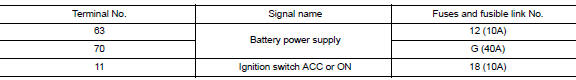
Is the fuse blown? Yes >> replace the blown fuse or fusible link after repairing the affected circuit.
No >> go to 2.
2.Check power supply circuit
- Turn ignition switch off.
- Disconnect bcm connectors.
- Check voltage between bcm connector and ground.
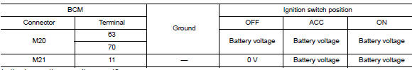
Is the inspection result normal? Yes >> go to 3.
No >> repair harness or connector.
3.Check ground circuit
Check continuity between bcm connector and ground.
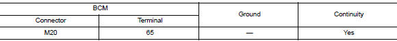
Is the inspection result normal? Yes >> inspection end.
No >> repair harness or connector.
Combination switch input circuit
Diagnosis procedure
Regarding wiring diagram information, refer to bcs-111, "wiring diagram".
1.Check input 1 - 5 circuit for open
- Turn ignition switch OFF.
- Disconnect bcm and combination switch connectors.
- Check continuity between BCM connector and combination switch connector.
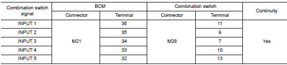
Is the inspection result normal? Yes >> go to 2.
No >> repair harness or connectors.
2.Check input 1 - 5 circuit for short
Check for continuity between bcm connector and ground.
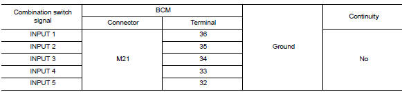
Is the inspection result normal? Yes >> repair harness or connectors.
No >> go to 3.
3.Check bcm output voltage
- Connect BCM connector.
- Check voltage between bcm connector and ground.
Is the inspection result normal? Yes >> replace combination switch.
No >> replace bcm. Refer to bcs-126, "removal and installation".
Combination switch output circuit
Diagnosis procedure
Regarding Wiring Diagram information, refer to BCS-111, "Wiring Diagram".
1.Check output 1 - 5 circuit for open
- Turn ignition switch off.
- Disconnect bcm and combination switch connectors.
- Check continuity between bcm connector and combination switch connector.
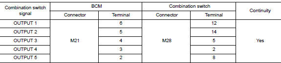
Is the inspection result normal? Yes >> go to 2.
No >> repair harness or connectors.
2.Check output 1 - 5 circuit for short
Check for continuity between bcm connector and ground.
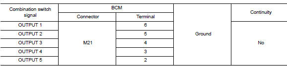
Is the inspection result normal? Yes >> repair harness or connectors.
No >> go to 3.
3.Check bcm input signal
- Connect BCM and combination switch connectors.
- Turn on any switch in the system that is malfunctioning.
- Check voltage between bcm connector and ground.
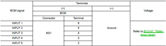
Is the inspection result normal? Yes >> replace bcm. Refer to bcs-126, "removal and installation".
No >> replace combination switch.
 Basic inspection
Inspection and adjustment
Additional service when replacing control unit (bcm)
Additional service when replacing control unit (bcm) : description
Before replacement
When replacing BCM, save or pr ...
 Symptom diagnosis
Combination switch system symptoms
Symptom Table
Perform the data monitor of consult to check for any malfunctioning
item.
Check the malfunction combinations.
Identify the malfunct ...
Other materials:
Slide front armrest (if so equipped)
To adjust the front armrest, take the leather cover
and slide it to the front or rear.
...
Headlamp (hi) circuit
Description
The IPDM E/R (intelligent power distribution module engine room) controls the
headlamp high relay based on
inputs from the BCM over the CAN communication lines. When the headlamp high
relay is energized, power
flows through fuses 41 and 42, located in the IPDM E/R. Power then flo ...
Engine control system
Symptom Table
SYSTEM — BASIC ENGINE CONTROL SYSTEM
1 - 6: The numbers refer to the order of inspection.
(continued on next table)
SYSTEM — ENGINE MECHANICAL & OTHER
1 - 6: The numbers refer to the order of inspection. ...
