Nissan Sentra Service Manual: Drive plate
Exploded View
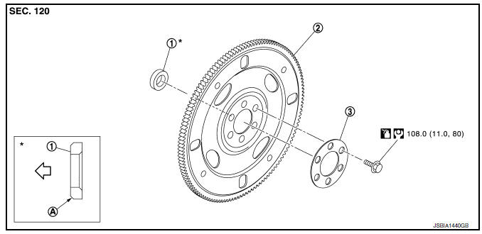
- Pilot converter
- Drive plate
- Reinforcement plate
- Chamfered
Removal and Installation
REMOVAL
- Remove the engine and the transaxle assembly from the vehicle, and separate the transaxle from the engine. Refer to EM-86, "CVT : Exploded View".
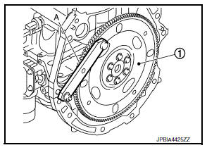
- Remove drive plate.
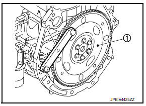
- Secure drive plate (1) using Tool (A), and remove bolts using suitable tool.
Tool number : KV11105210 (J-44716)
Tool number : KV11105210 (J-44716)
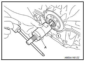
- Remove pilot converter (1), from the rear end of the crankshaft.
Use Tool (A), if necessary.
Tool number : ST16610000 (J-23907)
INSTALLATION
- Install pilot converter (1), drive plate (2) and reinforcement plate (3) as shown.
(A) : Crankshaft rear end
(B) : Rounded
- Using a drift of 33 mm (1.30 in) in diameter, press-fit pilot converter into the end of crankshaft until it stops.
- Install drive plate.
- Secure drive plate (1) using Tool (A), and install bolts using suitable tool.
Tool number : KV11105210 (J-44716)
CAUTION:
Be careful not to damage or scratch contact surface.
Inspection
DRIVE PLATE DEFLECTION
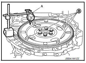
- Measure the deflection of drive plate contact surface to torque converter with a dial indicator (A).
- Measure the deflection at the area limited between 12.4 mm (0.488 in) dia and 20.0 mm (0.787 in) dia around hole (B).
Limit : 0.35 mm (0.0138 in) or less.
- If measured value is out of the standard, replace drive plate.
 Flywheel
Exploded View
Flywheel
Removal and Installation
REMOVAL
Remove the engine and the transaxle assembly from the vehicle, and
separate the transaxle from the
engine. Refer to TM-28, ...
 Cylinder block
Exploded View
Cylinder block
Block heater (for Canada)
Top ring
Second ring
Oil ring
Piston
Piston pin
Snap ring
Connecting rod
Connecting rod bearing (upper)
Connecting r ...
Other materials:
Precautions
Precaution for supplemental restraint system (srs) "air bag" and "seat belt
pre-tensioner"
The supplemental restraint system such as ą▓ąéčÜair bagą▓ąéč£ and ą▓ąéčÜseat belt pre-tensionerą▓ąéč£,
used along
with a front seat belt, helps to reduce the risk or severity of injur ...
Symptom diagnosis
Door does not lock/unlock with door lock and unlock switch
All door
ALL DOOR : Description
All doors do not lock/unlock using door lock and unlock switch.
ALL DOOR : Diagnosis Procedure
1.CHECK DOOR LOCK AND UNLOCK SWITCH
Check door lock and unlock switch.
Refer to DLK-97, "Component F ...
Making a call
To make a call from a phone connected to the
vehicleŌĆÖs Bluetooth┬« Hands-Free Phone System:
NOTE:
Available commands different if system is
in Manual Control mode. See ŌĆ£Manual ControlŌĆØ
in this section for more information.
Press the button.
The system will prompt you for a command. ...
