Nissan Sentra Service Manual: Door handle
Front door handle
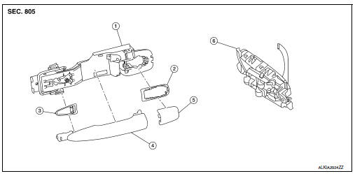
Front door handle : exploded view
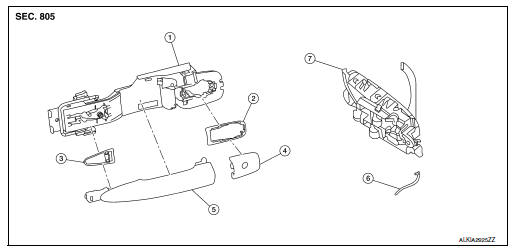
- Outside handle bracket
- Rear gasket
- Front gasket
- Outside handle escutcheon
- Outside handle
- Door key cylinder rod
- Inside handle assembly
Front door handle : removal and installation - inside handle
REMOVAL
- Remove front door finisher. Refer to INT-15, "Removal and Installation".
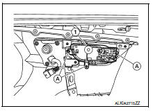
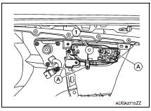
- Remove inside handle assembly screws (A) and the inside handle assembly (1).
INSTALLATION
Installation is in the reverse order of removal.
CAUTION:
- Check front door lock cables are properly engaged to inside handle.
- After installation, check front door open/close, lock/unlock operation.
Front door handle : removal and installation - outside handle
REMOVAL
- Fully close front door glass.
- Remove front door finisher. Refer to INT-15, "Removal and Installation".
- Remove front door vapor barrier.
- Remove front door glass channel rear.
- Disconnect the harness connectors from the door antenna and door request switch and then remove harness clamp on outside handle bracket.
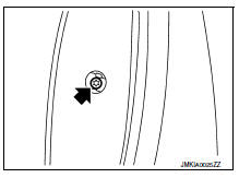
- Remove door side grommet, and loosen screw that retains the front door outside handle bracket.
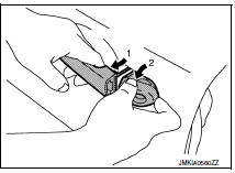
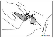
- Reach in to separate door key cylinder rod (LH side) (1) from door key cylinder assembly (LH side).
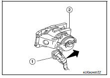
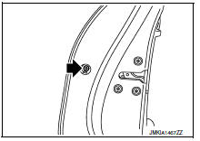
- While pulling outside handle (1), remove door key cylinder assembly (LH side) or outside handle escutcheon (2) (RH side).
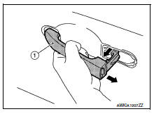
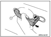
- While pulling outside handle (1), slide toward rear of vehicle to remove outside handle.
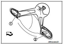
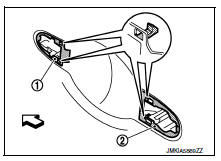
- Remove front gasket (1) and rear gasket (2).
 Front
Front
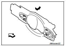
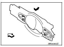
- Slide outside handle bracket toward rear of vehicle to remove.
 Front
Front
- Disconnect the outside handle cable from the outside handle bracket connection.
INSTALLATION
Installation is in the reverse order of removal.
CAUTION:
- When installing do not reuse front door outside handle bracket screw. Always replace screw with new ones when removed.
- When installing door key cylinder rod on the LH front door, be sure to rotate door key cylinder rod holder until a click is felt.
- Check front door lock cable is properly engaged to outside handle bracket.
- After installation, check front door open/close, lock/unlock operation.
Rear door handle
Rear door handle : exploded view
- Outside handle bracket
- Rear gasket
- Front gasket
- Outside door handle
- Outside handle escutcheon
- Inside handle assembly
Rear door handle : removal and installation - inside handle
REMOVAL
- Remove rear door finisher. Refer to INT-19, "Removal and Installation".
- Remove inside handle assembly screws (A) and inside handle assembly (1).
INSTALLATION
Installation is in the reverse order of removal.
CAUTION:
- Check rear door lock cables are properly engaged to inside handle.
- After installation, check rear door open/close, lock/unlock operation.
Rear door handle : removal and installation - outside handle
REMOVAL
- Fully close rear door glass.
- Remove rear door finisher. Refer to INT-19, "Removal and Installation".
- Remove rear door vapor barrier.
- Remove door side grommet, and loosen screw that retains the rear door outside handle bracket.
- While pulling outside handle (1), remove outside handle escutcheon (2).
- While pulling outside handle (1), slide toward rear of vehicle to remove outside handle.
- Remove front gasket (1) and rear gasket (2).
 : Front
- Slide outside handle bracket toward rear of vehicle to remove.
 : Front
- Remove clip and disconnect the outside handle cable from the outside handle bracket.
INSTALLATION
Installation in the reverse order of removal.
CAUTION:
- When installing do not reuse rear door outside handle bracket screw. Always replace screw with new ones when removed.
- Check rear door lock cable is properly engaged to outside handle bracket.
- After installation, check rear door open/close, lock/unlock operation.
 Rear door
Door assembly
Door assembly : removal and installation
Caution:
Use two people when removing or installing the rear door assembly
due to its heavy weight.
When removing and installing rear ...
 Door lock
Front door lock
Front door lock : exploded view
Outside handle bracket
Front gasket
Outside handle
Door lock assembly
Door striker
Door key cylinder rod
Inside handle assembly
Ou ...
Other materials:
P2857 Clutch A Pressure
DTC Logic
DTC DETECTION LOGIC
DTC
CONSULT screen terms
(Trouble diagnosis content)
DTC detection condition
Possible causes
P2857
CLUTCH A PRESSURE
(Clutch A Pressure Engagement
Performance)
The auxiliary gearbox gear ratio is 2.232 or
more for the auxili ...
Headlamp (hi) circuit
Description
The IPDM E/R (intelligent power distribution module engine room) controls the
headlamp high relay based on
inputs from the BCM over the CAN communication lines. When the headlamp high
relay is energized, power
flows through fuses 41 and 42, located in the IPDM E/R. Power then flo ...
Front coil spring and strut
Exploded View
Piston rod lock nut
Strut mount insulator
Strut mount bearing
Bound bumper
Coil spring
Lower rubber seat
Strut
Steering knuckle
Front
Removal and Installation
REMOVAL
Remove the wheel and tire using power tool. Refer to WT-47, "Exploded
View&quo ...
