Nissan Sentra Service Manual: Diagnosis and repair workflow
Work flow
Overall sequence
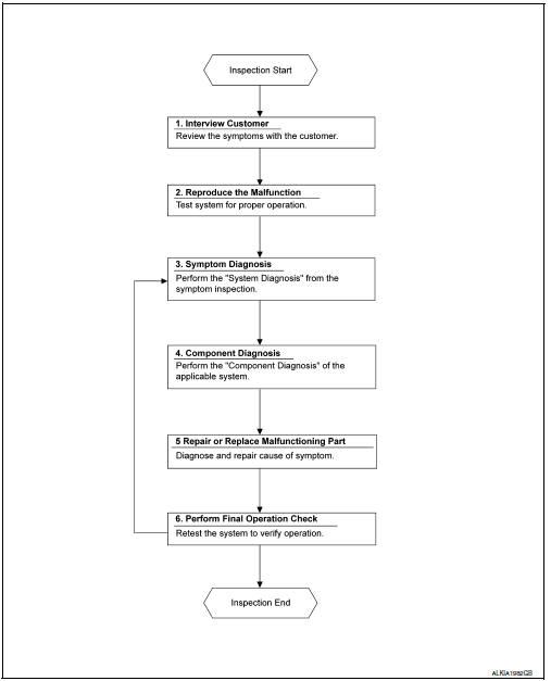
Detailed flow
1. Obtain information about symptom
Interview the customer to obtain as much information as possible about the conditions and environment under which the malfunction occurred.
>> GO TO 2.
2. Confirm concern
Check the malfunction on the vehicle that the customer describes.
Inspect the relation of the symptoms and the condition when the symptoms occur.
>> Go to 3.
3. Identify the malfunctioning system with symptom diagnosis
Use Symptom diagnosis from the symptom inspection result in step 2 and then identify where to start performing the diagnosis based on possible causes and symptoms.
>> GO TO 4.
4. Perform the component diagnosis of the applicable system
Perform the diagnosis with Component diagnosis of the applicable system.
>> GO TO 5.
5. Repair or replace the malfunctioning parts
Repair or replace the specified malfunctioning parts.
>> Go to 6.
6. Final check
Check that malfunctions are not reproduced when obtaining the malfunction information from the customer, referring to the symptom inspection result in step 2.
Are the malfunctions corrected? Yes >> inspection end.
No >> go to 3.
 Basic inspection
...
 Inspection and adjustment
Additional service when replacing control unit
Additional service when replacing control unit : description
Memory reset procedure
Please observe the following instructions at confirming the moo ...
Other materials:
P099C Shift solenoid G
DTC Logic
DTC
CONSULT screen terms
(Trouble diagnosis content)
DTC detection condition
Possible causes
P099C
SHIFT SOLENOID G
(Shift Solenoid G Control Circuit
High)
The TCM high clutch & reverse brake solenoid
valve current monitor reading is 200 mA ...
Precaution
Precaution for supplemental restraint system (srs) "air bag" and "seat belt
pre-tensioner"
The Supplemental Restraint System such as ą▓ąéčÜAIR BAGą▓ąéč£ and ą▓ąéčÜSEAT BELT
PRE-TENSIONERą▓ąéč£, used along
with a front seat belt, helps to reduce the risk or severity of injur ...
U1000 Can comm circuit
Description
CAN (Controller Area Network) is a serial communication line for real-time
application. It is an on-vehicle multiplex
communication line with high data communication speed and excellent malfunction
detection ability.
Many electronic control units are equipped onto a vehicle, an ...
