Nissan Sentra B18 (2020-2025) Service Manual: Control Cable
Exploded View
Exploded View
|
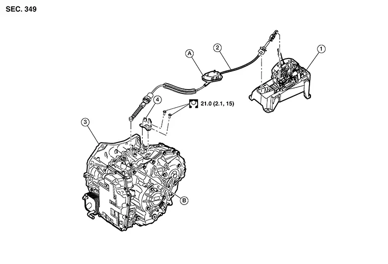
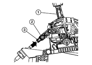
1. |
CVT shift selector assembly |
2. |
Control cable |
3. |
Transaxle assembly |
|
4. |
Bracket |
A. |
Grommet |
B. |
Manual lever |
Removal and Installation
Removal and Installation
CAUTION:
Always apply the parking brake before performing removal and installation.
REMOVAL
Apply the parking brake.
CAUTION:
Make sure the Nissan Sentra vehicle does not move with the parking brake applied.
Remove the exhaust front tube. Refer to Exploded View.
Remove nuts (A) and remove heat
shield. 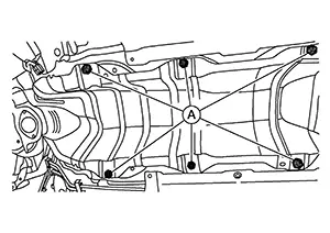
Remove battery tray. Refer to Removal and Installation.
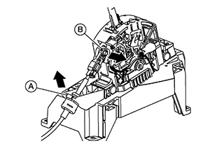
Using a suitable tool, disconnect
control cable (1) from manual lever as shown ( ).
). 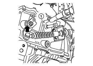
While pressing the lock of the selector
cables in the direction shown, remove the selector cable from the
CVT cable bracket. 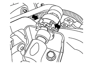
Remove the center console. Refer to Removal and Installation.
Remove the control cable from the CVT shift selector with the following procedure:
Remove control cable (A) from shift selector as
shown ().
Remove control cable (B) from CVT shift selector
in the direction shown ().
Release pawls (B) using suitable
tool, and pull grommet (A) downward to remove. 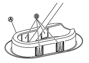
Remove the control cable from the Nissan Sentra vehicle.
INSTALLATION
Installation is in the reverse order of removal.
-
After installing control cable, perform adjustment procedure. Refer to Inspection and Adjustment.
-
From below the Nissan Sentra vehicle, press the grommet (A) into place until the pawls make a click sound.
CAUTION:
-
Place the grommet on the floor, then fasten it in place from below the Nissan Sentra vehicle.
-
Check that pulling down on the grommet does not disconnect it.
-
-
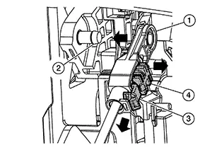
Pay attention to the following when connecting the control cable to the CVT shift selector.
-
Before connecting the control cable (1) to the CVT shift selector assembly (2), make sure the slider (3) is open and the lock (4) is pulled out as shown.
-
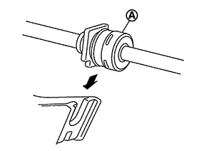
Install the socket (A) onto the CVT shift selector.
CAUTION:
-
Place the socket onto the CVT shift lever, then fasten it in place from above.
-
Check that pulling on the socket does not disconnect it.
-
-
Perform adjustment procedure. Refer to Inspection and Adjustment.
Inspection and Adjustment
Inspection and Adjustment
ADJUSTMENT OF CONTROL CABLE
Shift the selector lever to the “P” position.
CAUTION:
Rotate the wheels at least a quarter turn and be certain the Park position mechanism is fully engaged.
Make sure the lock is in the open position before adjusting the cable. Refer to Removal and Installation.
Push the stopper (2) in, until it
snaps into place.
Push the slider (3) until it snaps into place.
Push the selector lever (1) forward to confirm the adjustment is locked, you may hear a click.
INSPECTION AFTER INSTALLATION
Check the CVT position. Refer to Inspection.
Other materials:
Heated Seat Lh Relay
Component Function Check
Component Function
Check
CHECK HEATED SEAT LH RELAY FUNCTION
Check that seat cushion and seat back warm to the
preset temperature when operating the heated seat switch LH to HIGH
and LOW.
...
Intelligent Key Unit. Removal and Installation
Removal and Installation
Removal and Installation
REMOVAL
CAUTION:
Be sure to perform “ADDITIONAL
SERVICE WHEN REPLACING INTELLIGENT KEY UNIT” when replacing
Intelligent Key unit. Refer to Work Procedure.
Remove
instrument panel assembly. Refer to Removal and ...
P01f0 Engine Coolant Temperature
Dtc Description
DTC Description
DTC DETECTION LOGIC
DTC
CONSULT screen terms
(Trouble diagnosis
content)
DTC detection
condition
...