Nissan Sentra Service Manual: Connector symbols
Most of connector symbols in wiring diagrams are shown from the terminal side.
- Connector symbols shown from the terminal side are enclosed by a single line and followed by the direction mark.
- Connector symbols shown from the harness side are enclosed by a double line and followed by the direction mark.
- Certain systems and components, especially those related to
OBD, may use a new style slide-locking type harness connector.
For description and how to disconnect, refer to PG section, “Description”, “HARNESS CONNECTOR”.
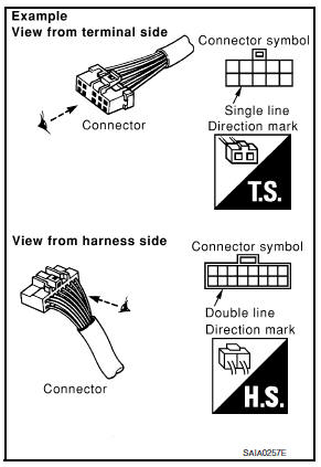
- Male and female terminals
Connector guides for male terminals are shown in black and female terminals in white in wiring diagrams.

 Sample/wiring diagram -example-
For detail, refer to following GI-11, "Description".
...
Other materials:
Brake pedal
Inspection
BRAKE PEDAL HEIGHT
Check the brake pedal height (H1) between the dash lower panel (1)
and the brake pedal upper surface.
Brake pedal height (H1) : Refer to BR-54, "Brake Pedal".
CAUTION:
Check the brake pedal height with the floor trim removed.
STOP LAMP SWITCH AND BR ...
System description
Component parts
Component parts location
Front tweeter lh (if equipped)
Steering switches
Audio unit
Front tweeter rh (if equipped)
Microphone (if equipped)
Front door speaker lh
Front door speaker RH
Rear speaker rh
Rear speaker lh
Antenna amp.
Window antenna
Bluetoot ...
P0846 Transmission fluid pressure SEN/SW B
DTC Logic
DTC DETECTION LOGIC
DTC
CONSULT screen terms
(Trouble diagnosis content)
DTC detection condition
Possible causes
P0846
TRANSMISSION FLUID
PRESSURE SEN/SW B
(Transmission Fluid Pressure
Sensor/Switch B Circuit
Range/Performance)
The detection ...
