Nissan Sentra B18 (2020-2025) Service Manual: Connector Symbols
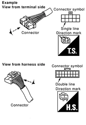
Most of the connector symbols in wiring diagrams are shown from the terminal side.
-
Connector symbols shown from the terminal side are enclosed by a single line and followed by the direction mark.
-
Connector symbols shown from the harness side are enclosed by a double line and followed by the direction mark.
-
Certain systems and components, especially those related to OBD, may use a new style slide-locking type harness connector. For description and how to disconnect, refer to PG section, “Description”, “HARNESS CONNECTOR”.
-
Male and female terminals
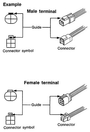
Connector guides for male terminals are shown in black and female terminals in white in wiring diagrams.

 Sample/wiring Diagram -Example-
Sample/wiring diagram -example-
Each section includes wiring diagrams.
Description
No.
Item ...
Other materials:
B0012-09 Active Vent
Dtc Description
DTC Description
DTC DETECTION LOGIC
DTC No.
CONSULT screen items
(Trouble diagnosis
content)
DTC Detection Condition
...
Fusible Link
Fusible Link
A melted fusible link can be detected either by
visual inspection or by feeling with a finger tip. If its condition
is questionable, use circuit tester or test lamp.
1
: Fusible link
...
Component Parts
Eco Mode System
Component Parts Location
Component Parts
Location
A.
Instrument lower panel LH
No.
...
