Nissan Sentra B18 (2020-2025) Service Manual: Component Parts
Intelligent Cruise Control System
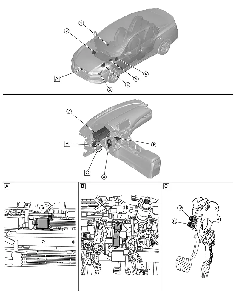
Component Parts Location
Component Parts Location
|
A. |
Front bumper fascia area (view with front bumper fascia removed) |
B. |
Left side of instrument panel (view with instrument lower panel LH removed) |
C. |
Brake pedal area (view with of brake pedal assembly removed) |
|
No. |
Component |
Function |
|---|---|---|
|
1. |
ADAS (Advanced Driver Assistance System) control unit 2 |
Refer to ADAS Control Unit 2. Refer to Component Parts Location for detailed component location. |
|
2. |
ABS (Anti-lock Braking System) actuator and electric unit (control unit) |
Refer to Component Parts Location for detailed component location. |
|
3. |
TCM (Transmission Control Module) (with CVT) |
TCM transmits the signal related to CVT control to ADAS control unit 2 via CAN communication. Refer to Component Parts Location for detailed component location. |
|
4. |
ECM (Engine Control Module) |
Refer to Component Parts Location for detailed component location. |
|
5. |
Clutch master cylinder (clutch switch) (with M/T) |
Transmits the clutch master cylinder (clutch switch) signal to the ECM. Refer to Exploded view for detailed component location. |
|
6. |
BCM (Body Control Module) |
BCM transmits the stop lamp switch signal and brake pedal position switch signal to ADAS control unit 2 via CAN communication. Refer to Component Parts Location for detailed component location. |
|
7. |
Combination meter (Information display) |
|
|
8. |
Chassis control module (with built in steering angle sensor) |
Measures the rotation amount, rotation speed, and rotation direction of steering wheel, and then transmits them to ADAS control unit 2 via CAN communication. Refer to Component Parts Location for detailed component location. |
|
9. |
ICC (Intelligent Cruise Control) steering switch |
Controls the ICC system by driver input. Refer to ICC Steering Switch. |
|
10. |
Distance sensor |
Refer to Distance Sensor. Refer to Component Parts Location for detailed component location. |
|
11. |
Driver assistance buzzer |
Refer to Driver Assistance Buzzer. Refer to Component Parts Location for detailed component location. |
|
12. |
Brake pedal position switch |
Refer to Brake Pedal Position Switch/Stop Lamp Switch. Refer to Component Parts Location for detailed component location. |
|
13. |
Stop lamp switch |
Icc Steering Switch
ICC Steering Switch
FUNCTIONS WITHIN THE SYSTEM
-
ICC steering switch allows the ON/OFF of the Intelligent Cruise Control and the settings of a Nissan Sentra vehicle speed and distance between vehicles.
-
ICC steering switch signal is transmitted to ECM. ECM transmits the signal to the ADAS control unit 2 via CAN communication.
INDIVIDUAL FUNCTIONS WITHIN THE SYSTEM
-
ICC steering switch detects a switch operation by the driver.
INDIVIDUAL OPERATION
-
The steering switch is composed of a combination of a normal open switch and a resistor.
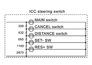
-
When each switch is pressed, the ECM detects which switch is operated according to input voltage.
PARTS LOCATION
Refer to Component Parts Location.
Component Description
Component Description
FUNCTIONS WITHIN THE SYSTEM
-
Steering assist switch allows the ON/OFF of steering assistance function.
INDIVIDUAL FUNCTIONS WITHIN THE SYSTEM
-
Transmits a steering assist switch signal to ADAS control unit 2.
INDIVIDUAL OPERATION
-
Steering assist switch changes the switch operation of driver to the voltage change (ON: 0V / OFF: 12V)
-
ECU reads the state of the switch by the voltage change.
PARTS LOCATION
Refer to Component Parts Location.
Other materials:
Unit Disassembly and Assembly
Front Combination Lamp
Exploded View
Exploded View
1.
Front combination lamp
2.
Turn/parking lamp bulb
...
Power Supply and Ground Circuit
A/c Amp.
Diagnosis Procedure
Diagnosis Procedure
CHECK A/C AMP. GROUND CIRCUIT FOR
OPEN
Ignition switch OFF.
Disconnect A/C amp. connector.
...
P27b5-00 Control Module
Dtc Description
DTC Description
DTC DETECTION LOGIC
DTC
CONSULT screen terms
(Trouble diagnosis
content)
DTC detection
conditi ...