Nissan Sentra B18 (2020-2025) Service Manual: Component Parts
Brake Control System
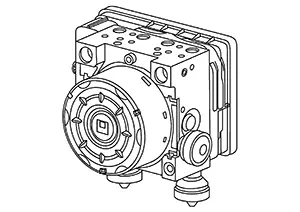
Component Parts Location
Component Parts Location
|
A. |
Right side of engine compartment |
B. |
Left side of engine compartment |
C. |
Left front wheel area (RH similar) |
|
D. |
Brake pedal area |
E. |
Left side of instrument panel (view with component removed from Nissan Sentra vehicle) |
F. |
Left side of instrument panel (view with component removed from Nissan Sentra vehicle) |
|
G. |
Steering wheel area (view with steering wheel removed) |
H. |
Left rear wheel area (RH similar) |
||
|
No. |
Component |
Function |
|---|---|---|
|
1. |
BCM (Body Control Module) |
Mainly transmits the following signals to ABS actuator and electric unit (control unit) via CAN communication:
Refer to Component Parts Location for detailed component location. |
|
2. |
ABS (Anti-lock Braking System) actuator and electric unit (control unit) |
Refer to ABS Actuator and Electric Unit (Control Unit). |
|
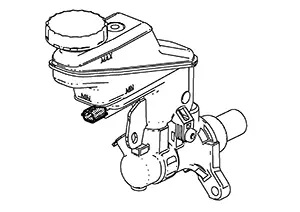
3. |
Brake fluid level switch |
Refer to Brake Fluid Level Switch. |
|
4. |
Vacuum sensor |
Refer to Vacuum Sensor. |
|
5. |
Front wheel sensor LH (RH similar) |
Refer to Wheel Sensor and Sensor Rotor. |
|
6. |
Brake pedal position switch |
Detects the operation status of brake pedal and transmits converted electric signal to ABS actuator and electric unit (control unit). |
|
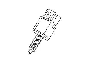
7. |
Stop lamp switch |
Refer to Stop Lamp Switch. |
|
8. |
Combination meter |
Mainly transmits the following signals to ABS actuator and electric unit (control unit) via CAN communication:
Mainly receives the following signals from ABS actuator and electric unit (control unit) via CAN communication:
Refer to Combination Meter (VDC OFF signal). |
|
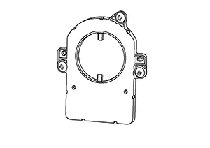
9. |
Chassis control module (with built in steering angle sensor) |
Mainly transmits the following signals to ABS actuator and electric unit (control unit) via CAN communication:
Refer to Chassis Control Module (With Built In Steering Angle Sensor) for detailed component location. |
|
10. |
Rear wheel sensor LH (RH similar) |
Refer to Wheel Sensor and Sensor Rotor. |
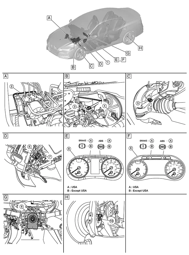
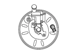
Wheel Sensor and Sensor Rotor
Wheel Sensor and Sensor Rotor
Note:
-
Wheel sensor of front wheel is installed on steering knuckle.
-
Sensor rotor of front wheel is integrated into the wheel hub assembly.
-
Wheel sensor of rear wheel is installed on rear final drive.
-
Sensor rotor of rear wheel is installed on drive shaft (rear final drive side).
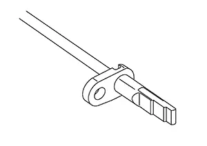
-
Never measure resistance and voltage value using a tester because sensor is an active sensor.
-
Power supply is supplied to detection portion so that magnetic field line is read. Magnetic field that is detected is converted to current signal.
-
When sensor rotor rotates, magnetic field changes. Magnetic field change is converted to current signals (rectangular wave) and is transmitted to ABS actuator and electric unit (control unit). Change of magnetic field is proportional to wheel speed.
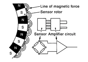
Abs Actuator and Electric Unit (control Unit)
ABS Actuator and Electric Unit (Control Unit)
The ABS actuator and electric unit (control unit) is located the right side of the engine room.
Electric unit (control unit) is integrated with actuator and comprehensively controls VDC function, TCS (Traction Control System) function, ABS function, EBD (Electric Brake Distribution) function and brake assist function.
ELECTRIC UNIT (CONTROL UNIT)
-
Brake fluid pressure, engine and transmission are controlled according to signals from each sensor.
-
If malfunction is detected, the system enters fail-safe mode.
ACTUATOR
The following components are integrated with ABS actuator:
Pump
Returns the brake fluid reserved in reservoir to master cylinder by reducing pressure.
Motor
Activates the pump according to signals from ABS actuator and electric unit (control unit).
Motor Relay
Operates the motor ON/OFF according to signals from ABS actuator and electric unit (control unit).
Actuator Relay
Operates each valve ON/OFF according to signals from ABS actuator and electric unit (control unit).
ABS IN Valve and ABS OUT Valve
Increases, holds or decreases the fluid pressure of each caliper according to signals from ABS actuator and electric unit (control unit).
Pressure Sensor
Detects the brake fluid pressure and transmits signal to ABS actuator and electric unit (control unit).
Cut Valve 1 (Primary Line) and Cut Valve 2 (Secondary Line)
Shuts off the ordinary brake line from master cylinder when VDC function, TCS function and brake assist function are activated.
Yaw Rate/Side/Decel G Sensor
Calculates the following information that affects the Nissan Sentra vehicle and transmits a signal to ABS actuator and electric unit (control unit): [Yaw rate/side/decel G sensor is integrated into the ABS actuator and electric unit (control unit).]
-
Nissan Sentra Vehicle rotation angular velocity (yaw rate signal)
-
Vehicle lateral acceleration (side G signal)
-
Nissan Sentra Vehicle longitudinal acceleration (decel G signal)
Stop Lamp Switch
Stop Lamp Switch
The stop lamp switch is attached to the brake pedal bracket near the brake pedal.
Detects the operation status of brake pedal and transmits converted electric signal to ABS actuator and electric unit (control unit).
Steering Angle Sensor
Steering Angle Sensor
The chassis control module (with built in steering angle sensor) is located behind the steering wheel.
Detects the following information and transmits steering angle signal to ABS actuator and electric unit (control unit) via CAN communication:
-
Chassis control module (with built in steering angle sensor) malfunction signal
-
Steering wheel rotation amount
-
Steering wheel rotation angular velocity
-
Steering wheel rotation direction
-
Intelligent trace control signal
Brake Fluid Level Switch
Brake Fluid Level Switch
The brake fluid level switch is located on the left side of the master cylinder reservoir.
Detects the brake fluid level in reservoir tank and transmits converted electric signal from combination meter to ABS actuator and electric unit (control unit) via CAN communication when brake fluid level is the specified level or less.
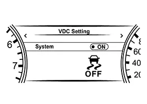
Combination Meter (vdc Off Signal)
Combination meter (VDC OFF Signal)
-
Non-operational status or standby status of the following functions can be selected using VDC OFF switch: VDC OFF indicator lamp indicates the operation status of function (ON: Non-operational status, OFF: Standby status).
- Type A meter
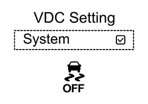
- Type B meter
-
Nissan Sentra Vehicle Dynamic Control function
-
Traction Control System function
-
Automatic Emergency Braking function
- Type A meter
ABS function and EBD function operate.
-
VDC OFF indicator lamp turns OFF (standby status) when the engine is started again after it is stopped once while VDC OFF indicator lamp is ON (non-operational status).
Vacuum Sensor
Vacuum Sensor
The brake fluid level switch is located on the left side of the brake booster.
Detects the vacuum in brake booster and transmits converted electric signal to ABS actuator and electric unit (control unit).
Other materials:
Active Grille Shutter
Component Inspection
Component Inspection
CHECK ACTIVE GRILLE SHUTTER
With CONSULT
Start the engine.
Select “ACTIVE GRILLE
SHUTTER” in “ACTIVE TEST” mode of
“ENGINE” using CONSULT.
...
Precautions for Refrigerant System Service
Precautions
For Refrigerant System Service
GENERAL REFRIGERANT PRECAUTION
Warning:
Do not breathe A/C refrigerant and oil vapor or
mist. Exposure may irritate eyes, nose and throat. Remove HFO-1234yf
(R-1234yf) from the A/C system, using certified s ...
U1300 Av Communication Circuit
Dtc Description
DTC Description
DTC DETECTION LOGIC
DTC No.
CONSULT screen terms
(Trouble diagnosis
content)
DTC detection condition
...