Nissan Sentra Service Manual: Component parts
Component parts location
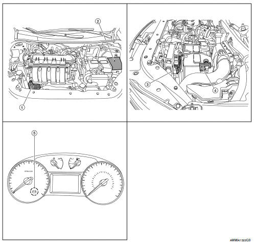
- Generator
- IPDM E/R (view with air inlet duct removed)
- ECM
- Battery current sensor
- Charge warning lamp indicator
Component description
| Component part | Description |
| Generator (IC regulator) | The IC regulator controls the power generation voltage
by the target
power generation voltage based on the received PWM command
signal.
When there is no PWM command signal, the generator performs the normal power generation according to the characteristic of the IC regulator. |
| IPDM E/R | The IPDM E/R converts the received power generation command value into a pulse width modulated (PWM) command signal and sends it to the IC regulator. |
| ECM | The battery current sensor detects the charging/discharging current
of the battery. The ECM judges the battery condition based on
this signal.
The ECM judges whether to request more output via the power generation voltage variable control according to the battery condition. When performing the power generation voltage variable control, the ECM calculates the target power generation voltage according to the battery condition and sends the calculated value as the power generation command value to the IPDM E/R. |
| Battery current sensor | The battery current sensor is located on the negative battery cable terminal. The battery current sensor detects the charging/discharging current of the battery and sends a voltage signal to the ECM according to the current value detected. |
| Combination meter (charge warning lamp) | The IC regulator warning function activates to illuminate the
charge warning lamp if any of the following symptoms occur while
generator is operating:
В·Excessive voltage is produced.
В·No voltage is produced. |

 Charging system
System Diagram
System Description
The generator provides DC voltage to operate the vehicle's electrical system
and to keep the battery charged.
The voltage output is controlled by the IC ...
Other materials:
P0453 EVAP Control system pressure sensor
DTC Logic
DTC DETECTION LOGIC
DTC No.
CONSULT screen terms
(Trouble diagnosis content)
DTC detecting condition
Possible cause
P0453
EVAP SYS PRES SEN
(Evaporative emission system
pressure sensor/switch high)
An excessively high voltage from the
sensor is ...
Front wiper motor ground circuit
Diagnosis procedure
Regarding Wiring Diagram information, refer to WW-24, "Wiring Diagram - With
Intelligent Key" or WW-29,
"Wiring Diagram - Without Intelligent Key".
1.Check front wiper motor (gnd) open circuit
Turn the ignition switch OFF.
Disconnect front wiper mot ...
Daytime light relay circuit
Description
The bcm sends a daytime light request to the ipdm e/r via the can
communication lines. The power flows
through fuse 29 located in fuse block j/b to the daytime light relay coil. When
the ipdm e/r operates the daytime
light relay, power is sent to the daytime lamps.
Diagnosis proc ...
