Nissan Sentra Service Manual: C1601 Battery power supply
DTC Logic
DTC DETECTION LOGIC
| DTC | Display item | Malfunction detected condition | Possible cause |
| C1601 | BATTERY VOLT | When a power supply voltage to the EPS control unit is maintained at 17.5 V or more or at less than 9 V continuously for five second or more. |
|
DTC CONFIRMATION PROCEDURE
1.PRECONDITIONING
If DTC CONFIRMATION PROCEDURE has been previously conducted, always turn ignition switch OFF and wait at least 10 seconds before conducting the next test.
>> GO TO 2.
2.DTC REPRODUCTION PROCEDURE
 With CONSULT
-
Turn the ignition switch OFF to ON.
-
Perform EPS self-diagnosis.
Is DTC C1601 detected? YES >> Proceed to diagnosis procedure. Refer to STC-22, "Diagnosis Procedure".
NO >> Inspection End.
Diagnosis Procedure
Regarding Wiring Diagram information, refer to STC-15, "Wiring Diagram".
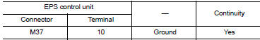
1.Check EPS Control unit ground circuit
-
Turn ignition switch OFF.
-
Disconnect EPS control unit harness connector.
-
Check continuity between EPS control unit harness connector terminal and ground.
-
Connect EPS control unit harness connector.
Is the inspection result normal? YES >> GO TO 2.
NO >> Repair open circuit or short to ground or short to power in harness or connectors.
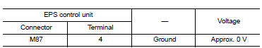
2.Check EPS Control unit power supply circuit (1)
-
Check voltage between EPS control unit harness connector terminals and ground.
Is the inspection result normal? YES >> GO TO 4.
NO >> GO TO 3.
3.Check EPS Control unit power supply circuit
(2)
-
Turn ignition switch OFF.
-
Check the 10A fuse (#5).
-
Check the harness for open or short between EPS control unit harness connector terminal 4 and the 10A fuse (#5).
Is the inspection result normal? YES >> Perform the trouble diagnosis for ignition power supply circuit. Refer to PCS-70, "Wiring Diagram".
NO >> Repair or replace the malfunctioning parts.
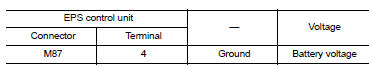
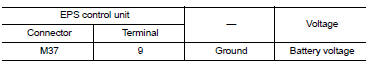
4.Check EPS Control unit power supply circuit (3)
-
Turn ignition switch OFF.
-
Check voltage between EPS control unit harness connector terminals and ground.
-
Turn ignition switch ON.
CAUTION:
Never start the engine.
-
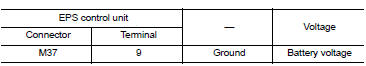
Check voltage between EPS control unit harness connector and ground.
Is the inspection result normal? YES >> GO TO 6.
NO >> GO TO 5.
5.CHECK EPS CONTROL UNIT POWER SUPPLY CIRCUIT (4)
-
Turn ignition switch OFF.
-
Check the 60A fusible link (#M).
-
Check the harness for open or short between EPS control unit harness connector terminal 9 and the 60A fusible link (#M).
Is the inspection result normal? YES >> Perform the trouble diagnosis for power supply circuit. Refer to PCS-70, "Wiring Diagram".
NO >> Repair or replace the malfunctioning parts.
6.CHECK TERMINALS AND HARNESS CONNECTORS
Check the EPS control unit pin terminals for damage or loose connection with harness connector.
Is the inspection result normal? YES >> EPS control unit is malfunctioning. Replace steering column assembly. Refer to ST-12, "Removal and Installation".
NO >> Repair or replace the malfunctioning parts.

 C1604 Torque sensor
DTC Logic
DTC DETECTION LOGIC
DTC
Display item
Malfunction detected condition
Possible cause
C1604
TORQUE SENSOR
When torque sensor output signal is malfunctioning
...
Other materials:
Service Notice or Precautions for Steering System
In case of removing steering gear assembly, make the final
tightening with grounded and unloaded vehicle
condition, and then check wheel alignment.
Observe the following precautions when disassembling.
Before disassembly, thoroughly clean the outside of the
unit.
...
OIL
Description
MAINTENANCE OF OIL LEVEL
The compressor oil is circulating in the system together with the
refrigerant. It is necessary to fill compressor
with oil when replacing A/C system parts or when a large amount of refrigerant
leakage is detected. It is important
to always maintain oil l ...
Diagnosis and repair workflow
Work Flow
OVERALL SEQUENCE
DETAILED FLOW
1. OBTAIN INFORMATION ABOUT SYMPTOM
Interview the customer to obtain as much information as possible about the
conditions and environment under
which the malfunction occurred.
>> GO TO 2.
2. CONFIRM THE SYMPTOM
Check the malfunction on the ...
