Nissan Sentra Service Manual: C1111 PUMP MOTOR
DTC Logic
DTC DETECTION LOGIC
| DTC | Display Item | Malfunction detected condition | Possible causes |
| C1111 | PUMP MOTOR |
|
|
DTC CONFIRMATION PROCEDURE
1.CHECK SELF DIAGNOSTIC RESULT
 With CONSULT
-
Turn ignition switch OFF.
-
Depress brake pedal 20 times or more.
-
Start the engine and wait for 3 minutes or more.
-
Perform self diagnostic result.
Is DTC C1111 detected? YES >> Proceed to diagnosis procedure. Refer to BRC-65, "Diagnosis Procedure".
NO >> Inspection End.
Diagnosis Procedure
Regarding Wiring Diagram information, refer to BRC-44, "Wiring Diagram".
1.CONNECTOR INSPECTION
-
Turn ignition switch OFF.
-
Disconnect ABS actuator and electric unit (control unit) connectors.
-
Check connectors and terminals for deformation, disconnection, looseness or damage.
Is the inspection result normal? YES >> GO TO 2.
NO >> Repair or replace as necessary.
2.Check abs motor and motor relay battery power supply
Check voltage between ABS actuator and electric unit (control unit) connector E33 terminal 1 and ground.
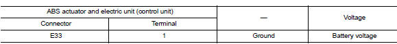
Is the inspection result normal? YES >> GO TO 3.
NO >> Repair or replace malfunctioning components.
3.Check ABS Actuator and electric unit (control unit) ground circuit
Check continuity between ABS actuator and electric unit (control unit) connector E33 terminals 13, 38 and ground.
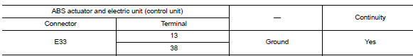
Is the inspection result normal? YES >> Replace ABS actuator and electric unit (control unit). Refer to BRC-110, "Removal and Installation".
NO >> Repair or replace malfunctioning components.
 1110, C1170 ABS Actuator and electric unit (control unit)
DTC Logic
DTC DETECTION LOGIC
DTC
Display item
Malfunction detected condition
Possible cause
C1110
CONTROLLER FAILURE
When there is an internal malfunction in the ABS ...
 C1113, C1145, C1146 Yaw rate/side/decel G Sensor
DTC Logic
DTC DETECTION LOGIC
DTC
Display Item
Malfunction detected condition
Possible causes
C1113
G SENSOR
When a malfunction is detected in longitunal G sensor
s ...
Other materials:
P1212 TCS Communication line
Description
This CAN communication line is used to control the smooth engine operation
during the TCS operation. Pulse
signals are exchanged between ECM and “ABS actuator and electric unit (control
unit)”.
Be sure to erase the malfunction information such as DTC not only for Đ˛Đ‚Ń ...
Precaution
Precaution for Supplemental Restraint System (SRS) "AIR BAG" and "SEAT
BELT PRE-TENSIONER"
The Supplemental Restraint System such as “AIR BAG” and “SEAT BELT PRE-TENSIONER”,
used along
with a front seat belt, helps to reduce the risk or severity of injur ...
Dtc/circuit diagnosis
Eco mode switch
Component function check
1. Check eco mode switch operation
Turn ignition switch ON.
Check ECO mode indicator lamp turns ON/OFF on combination meter when
turn ECO mode switch ON/
OFF.
Is the inspection result normal?
Yes >> inspection end
No >> go to dm ...
