Nissan Sentra Owners Manual: Booster seats
Precautions on booster seats
| WARNING If a booster seat and seat belt are not used properly, the risk of a child being injured in a sudden stop or collision greatly increases:
|
Booster seats of various sizes are offered by several manufacturers. When selecting any booster seat, keep the following points in mind:
- Choose only a booster seat with a label certifying that it complies with Federal Motor Vehicle Safety Standard 213 or Canadian Motor Vehicle Safety Standard 213.
- Check the booster seat in your vehicle to be sure it is compatible with the vehicle’s seat and seat belt system.
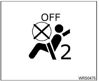
- Make sure the child’s head will be properly supported by the booster seat or vehicle seat. The seatback must be at or above the center of the child’s ears. For example, if a low back booster seat 1 is chosen, the vehicle seatback must be at or above the center of the child’s ears. If the seatback is lower than the center of the child’s ears, a high back booster seat 2 should be used.
- If the booster seat is compatible with your vehicle, place the child in the booster seat and check the various adjustments to be sure the booster seat is compatible with the child. Always follow all recommended procedures.
All U.S. states and Canadian provinces or territories require that infants and small children be restrained in an approved child restraint at all times while the vehicle is being operated.
The instructions in this section apply to booster seat installation in the rear seats or the front passenger seat.
Booster seat installation
CAUTION
Do not use the lap/shoulder belt in the Automatic Locking Retractor mode when using a booster seat with the seat belts.
Refer to all Warnings and Cautions in the “Child safety”, “Child restraints” and “Booster seats” sections before installing a child restraint.
Follow these steps to install a booster seat in the rear seat or in the front passenger seat:
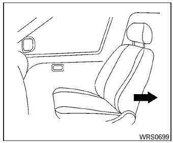
- If you must install a booster seat in the front seat, move the seat to the rearmost position.
- Position the booster seat on the seat. Only place it in a front-facing direction. Always follow the booster seat manufacturer’s instructions.
Front passenger position
- The booster seat should be positioned on
the vehicle seat so that it is stable.
If necessary, adjust or remove the head restraint/headrest to obtain the correct booster seat fit. If the head restraint/headrest is removed, store it in a secure place. Be sure to reinstall the head restraint/headrest when the booster seat is removed. See “Head restraints/headrests” in this section for head restraint/headrest adjustment, removal and installation information. If the seating position does not have an adjustable head restraint/headrest and it is interfering with the proper booster seat fit, try another seating position or a different booster seat.
- Position the lap portion of the seat belt low and snug on the child’s hips. Be sure to follow the booster seat manufacturer’s instructions for adjusting the seat belt routing.
- Pull the shoulder belt portion of the seat belt
toward the retractor to take up extra slack.
Be sure the shoulder belt is positioned across the top, middle portion of the child’s shoulder. Be sure to follow the booster seat manufacturer’s instructions for adjusting the seat belt routing.
- Follow the warnings, cautions and instructions for properly fastening a seat belt shown in “Three-point type seat belt with retractor” in this section.
- If the booster seat is installed in the front
passenger seat, place the ignition switch in
the ON position. The front passenger air bag
status light
 may or may not
illuminate, depending on the size of the child and the type of booster seat being used. See “Supplemental air bag warning light” in this section.
 Installing top tether strap
WARNINGChild restraint anchorages are designed
to withstand only those loads imposed by
correctly fitted child restraints. Under no
circumstances are they to be used to attach
a ...

Other materials:
P0122, P0123 TP Sensor
DTC Logic
DTC DETECTION LOGIC
NOTE:
If DTC P0122 or P0123 is displayed with DTC P0643, first perform the
trouble diagnosis for DTC P0643.
Refer to EC-353, "DTC Logic".
DTC No.
CONSULT screen terms
(Trouble diagnosis content)
DTC detecting condition
Possible caus ...
Radiator
Exploded View
Mounting rubber (upper)
Radiator
Mounting rubber (lower)
Radiator drain plug
Reservoir tank cap
Reservoir tank hose
Reservoir tank
Clamp
Radiator hose (lower)
Fan shroud and motor assembly
Radiator hose (upper)
Filler neck hose
Filler neck
Radiator fil ...
System
Meter system
Meter system : system diagram
Meter system : system description
COMBINATION METER
The combination meter receives signals from switches, sensors and modules to
control the following functions:
Speedometer/tachometer
Warning lamps
Indicator lamps
Meter illumination c ...
