Nissan Sentra B18 (2020-2025) Service Manual: Body Control System :: Removal and Installation
Bcm. Removal and Installation. Removal and Installation
Removal and Installation
CAUTION:
-
Before replacing BCM, perform “ADDITIONAL SERVICE WHEN REPLACING CONTROL UNIT (BCM)� to save or print current Nissan Sentra vehicle specification. Refer to Description.
-
When replacing the BCM, a new BCM must be used. The functions controlled by the BCM do not operate properly if a BCM from another Nissan Sentra vehicle is used.
REMOVAL
Disconnect the negative battery terminal. Refer to Removal and Installation (Battery).
Remove instrument lower panel LH. Refer to Removal and Installation.
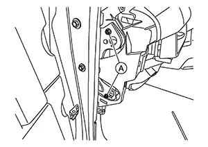
Remove fuse block (J/B) bolts (A)
and position BCM aside.
Remove the screws (A) and remove
the BCM (1) from bracket (B).
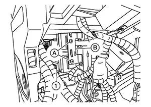
Disconnect the harness connectors and remove the BCM.
INSTALLATION
Installation is in the reverse order of removal.
CAUTION:
-
When replacing BCM, perform "ADDITIONAL SERVICE WHEN REPLACING CONTROL UNIT (BCM)". Refer to Description.
-
When replacing BCM, perform the system initialization (NATS). Refer to Description.
-
When replacing BCM, if new BCM does not come with keyfobs attached, all existing keyfobs must be re-registered. Refer to the CONSULT immobilizer mode and follow the on screen instructions.
-
For initialization and registration of Intelligent Keys. Refer to CONSULT Immobilizer mode and follow the on-screen instructions.
Combination Switch. Exploded View
Exploded View
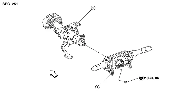
|
1. |
Steering column |
2. |
Combination switch |
|
Front |


Shown with the steering wheel removed for clarity only.
Removal and Installation
Removal and Installation
REMOVAL
CAUTION:
-
Before servicing, turn the ignition switch OFF, disconnect both battery terminals and wait at least three minutes.
-
Do not use air or electric tools when removing or installing the combination switch.
Remove the chassis control module (with built in steering angle sensor). Refer to Removal and Installation.
Loosen
screw (A). 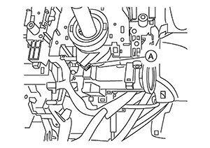
Disconnect the harness connector from the combination switch and remove.
INSTALLATION
Installation is in the reverse order of removal.
CAUTION:
-
After the work is completed, make sure no system malfunction is detected by air bag warning lamp.
-
In case a malfunction is detected by the air bag warning lamp, reset with the self-diagnosis function and delete the memory with CONSULT.
-
If a malfunction is still detected after the above operation, perform self-diagnosis to repair malfunctions. Refer to Description.
Other materials:
Periodic Maintenance
Engine Oil
Inspection
Inspection
ENGINE OIL LEVEL
Note:
Before starting engine, put Nissan Sentra vehicle horizontally
and check the engine oil level. If engine is already started, stop
it and allow 10 minutes before checking.
Pull out
oil level gauge and wipe it clean.
...
Seat. Preparation
Preparation
Special Service Tool
Special Service Tool
The actual shape of the tools may differ from those
illustrated here.
Tool number
(TechMate No.)
Tool name
...
NISSAN Intelligent Key
WARNING
Radio waves may adversely affect electronic medical equipment. Drivers
or passengers who use a pacemaker or similar medical device should consult the
device manufacturer regarding possible effects before using the NISSAN Intelligent
Key in the Nissan Sentra.
The Intelligent Ke ...