Nissan Sentra B18 (2020-2025) Service Manual: Blower Motor
Diagnosis Procedure
Diagnosis Procedure
-
CHECK FUSE
-
-
Ignition switch OFF.
-
Check 30A fuse [No. 55, located in fuse block (J/B)].
-
Is the inspection result normal?
YES >>GO TO 2.
NO >>Replace the blown fuse after repairing the affected circuit.
-
-
CHECK BLOWER MOTOR POWER SUPPLY
-
-
Disconnect blower motor connector.
-
Ignition switch ON.
-
Check voltage between blower motor harness connector and ground.
+
—
Voltage
(Approx.)
Blower motor
Connector
Terminal
M62
2
Ground
Battery voltage
-
Is the inspection result normal?
YES >>GO TO 3.
NO >>Repair harness or connector.
-
-
CHECK BLOWER MOTOR GROUND CIRCUIT
-
-
Ignition switch OFF.
-
Check continuity between blower motor harness connector and ground.
Blower motor
—
Continuity
Connector
Terminal
M62
4
Ground
Yes
-
Is the inspection result normal?
YES >>GO TO 4.
NO >>Repair harness or connector.
-
-
CHECK BLOWER MOTOR CONTROL SIGNAL CIRCUIT
-
-
Disconnect A/C amp. connector.
-
Check continuity between blower motor harness connector and A/C amp. harness connector.
Blower motor
A/C amp.
Continuity
Connector
Terminal
Connector
Terminal
M62
1
M81
34
Yes
-
Is the inspection result normal?
YES >>GO TO 5.
NO >>Repair the harness or connector.
-
-
CHECK BLOWER MOTOR CONTROL SIGNAL
-
-
Reconnect blower motor connector and A/C amp. connector.
-
Ignition switch ON.
-
Operate MODE switch to set air outlet to VENT.
-
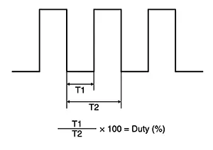
Change fan speed from Lo to Hi, and check duty ratios between blower motor harness connector and ground by using an oscilloscope.
Note:
Calculate drive signal duty ratio as shown in the figure.
T2 = Approx. 1.6 ms
Blower motor
Condition
Duty ratio
(Approx.)
Connector
Terminal
Fan speed (manual)
VENT mode
M62
1
1st
25 %
2nd
33 %
3rd
41 %
4th
51 %
5th
61 %
6th
69 %
7th
81 %
-
Is the inspection result normal?
YES >>Replace blower motor. Refer to Removal and Installation.
NO >>Replace A/C amp. Refer to Removal and Installation.
-
Component Inspection (blower Motor)
Component Inspection (Blower Motor)
-
CHECK BLOWER MOTOR
-
-
Connect battery voltage to terminal 2 of blower motor.
-
Connect ground to terminal 4 of blower motor.
-
Does the blower fan operate?
YES>>Intermittent incident. Refer to Intermittent Incident.
NO>>Replace blower motor. Refer to Removal and Installation.
-
Other materials:
Abs Warning Lamp
Component Function Check
Component Function Check
CHECK ABS WARNING LAMP FUNCTION
Check that ABS warning lamp in combination meter
turns ON for 1 second after ignition switch is placed ON.
CAUTION:
Never start th ...
Removal and Installation
Av Control Unit
Exploded View
Exploded View
1.
AV control unit bracket
(LH)
2.
AV control unit
...
B2f06-15 Back Door/trunk Opener Switch
Dtc Description
DTC Description
DTC DETECTION LOGIC
DTC No.
CONSULT screen items (Trouble
diagnosis content)
DTC detecting condition
...