Nissan Sentra Service Manual: Basic inspection
Diagnosis and repair workflow
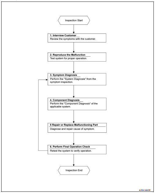
Work Flow
OVERALL SEQUENCE
DETAILED FLOW
1. OBTAIN INFORMATION ABOUT SYMPTOM
Interview the customer to obtain as much information as possible about the conditions and environment under which the malfunction occurred.
>> GO TO 2.
2. CONFIRM THE SYMPTOM
Check the malfunction on the vehicle that the customer describes.
Inspect the relation of the symptoms and the condition when the symptoms occur.
>> GO TO 3.
3. IDENTIFY THE MALFUNCTIONING SYSTEM WITH SYMPTOM DIAGNOSIS
Use Symptom diagnosis from the symptom inspection result in step 2 and then identify where to start performing the diagnosis based on possible causes and symptoms. Refer to WW-46, "Symptom Table".
>> GO TO 4.
4. PERFORM THE COMPONENT DIAGNOSIS OF THE OF THE APPLICABLE SYSTEM
Perform the diagnosis with Component diagnosis of the applicable system.
>> GO TO 5.
5. REPAIR OR REPLACE THE MALFUNCTIONING PARTS
Repair or replace the specified malfunctioning parts.
>> GO TO 6.
6. FINAL CHECK
Check that malfunctions are not reproduced when obtaining the malfunction information from the customer, referring to the symptom inspection result in step 2.
Are the malfunctions corrected? YES >> Inspection End.
NO >> GO TO 3.
 Wiring diagram
Wiper and washer system
Wiring diagram - with intelligent key
Wiring diagram - without intelligent key
...

Other materials:
C1116 Stop lamp switch
DTC Logic
DTC DETECTION LOGIC
DTC
Display item
Malfunction detected condition
Possible cause
C1116
STOP LAMP SW
When stop lamp switch circuit is open.
Harness or connector
Stop lamp switch
ABS actuator and electric unit
(control unit)
...
Tow Truck Towing
NISSAN recommends that vehicle be towed with driving (front) wheels off the
ground or that a dolly be used.
CVT: Continuously Variable Transmission
M/T: Manual transmission
CAUTION:
All applicable state or Provincial laws and local laws regarding
the towing operation must be ...
Mixture ratio self-learning value
clear
Description
This describes how to erase the mixture ratio self-learning value. For the
actual procedure, follow the instructions
in “Diagnosis Procedure”.
Work Procedure
1.START
With CONSULT
Start engine and warm it up to normal operating temperature.
Select “SELF-LEARNI ...
