Nissan Sentra B18 (2020-2025) Service Manual: B24a4-15 Intake Sensor
Dtc Description
DTC Description
DTC DETECTION LOGIC
|
DTC No. |
CONSULT screen terms (Trouble diagnosis content) |
DTC detection condition |
|
|---|---|---|---|
|
B24A4-15 |
INTAKE SENSOR (Intake sensor) |
Diagnosis condition |
Ignition switch ON |
|
Signal (Terminal) |
Intake sensor signal |
||
|
Threshold |
The intake sensor recognition temperature is too low [less than -44°F (-42°C)] |
||
|
Diagnosis delay time |
2 seconds or more |
||
POSSIBLE CAUSE
-
Intake sensor
-
A/C amp.
-
Harness or connectors (The sensor circuit is open or shorted to battery)
FAIL-SAFE
—
Confirmation Procedure
Confirmation Procedure
-
PERFORM DTC CONFIRMATION PROCEDURE
-
 CONSULT
-
Ignition switch ON.
-
Select “Self Diagnostic Result� mode of “HVAC�.
-
Check DTC.
-
Is DTC detected?
YES >>Refer to DTC Diagnosis Procedure.
NO >>To check malfunction symptom before repair: Refer to Intermittent Incident.
NO >>Confirmation after repair: Inspection End.
-
Dtc Diagnosis Procedure
DTC Diagnosis Procedure
-
CHECK INTAKE SENSOR SIGNAL
-
-
Ignition switch ON.
-
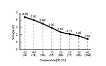
Check voltage between A/C amp. harness connector.
A/C amp.
Voltage
(Approx.)
Connector
Terminals
+
-
M81
23
26
-
Is the inspection result normal?
YES >>Replace A/C amp. Refer to Removal and Installation.
NO >>GO TO 2.
-
-
CHECK INTAKE SENSOR POWER SUPPLY
-
-
Ignition switch OFF.
-
Disconnect intake sensor connector.
-
Ignition switch ON.
-
Check voltage between intake sensor harness connector and ground.
+
-
Voltage
(Approx.)
Intake sensor
Connector
Terminal
M169
1
Ground
5 V
-
Is the inspection result normal?
YES >>GO TO 3.
NO >>GO TO 5.
-
-
CHECK INTAKE SENSOR GROUND CIRCUIT FOR OPEN
-
-
Ignition switch OFF.
-
Disconnect A/C amp. connector.
-
Check continuity between intake sensor harness connector and A/C amp. harness connector.
Intake sensor
A/C amp.
Continuity
Connector
Terminal
Connector
Terminal
M169
2
M81
26
Yes
-
Is the inspection result normal?
YES >>GO TO 4.
NO >>Repair harness or connector.
-
-
CHECK INTAKE SENSOR
-
Check intake sensor. Refer to Component Inspection.
Is the inspection result normal?
YES >>Replace A/C amp. Refer to Removal and Installation.
NO >>Replace intake sensor. Refer to Removal and Installation.
-
-
CHECK INTAKE SENSOR POWER SUPPLY CIRCUIT FOR OPEN
-
-
Ignition switch OFF.
-
Disconnect A/C amp. connector.
-
Check continuity between intake sensor harness connector and A/C amp. harness connector.
Intake sensor
A/C amp.
Continuity
Connector
Terminal
Connector
Terminal
M169
1
M81
23
Yes
-
Is the inspection result normal?
YES >>GO TO 6.
NO >>Repair harness or connector.
-
-
CHECK INTAKE SENSOR POWER SUPPLY CIRCUIT FOR SHORT
-
Check voltage between intake sensor harness connector and ground.
+
-
Voltage
(Approx.)
Intake sensor
Connector
Terminal
M169
1
Ground
0 V
Is the inspection result normal?
YES >>Replace A/C amp. Refer to Removal and Installation.
NO >>Repair harness or connector.
-
Other materials:
B2c20-12 Starter Cut Relay
Dtc Description
DTC Description
DTC DETECTION LOGIC
DTC No.
CONSULT screen items
(Trouble diagnosis
content)
DTC detecting condition
...
U0131 Can Communication
Dtc Description
DTC Description
DTC DETECTION LOGIC
DTC
CONSULT screen terms
(Trouble diagnosis
content)
DTC detection
condition
...
Operation
Switch Name and Function
Switch Name
and Function
OPERATION AND DISPLAY OF AUTOMATIC AIR CONDITIONING
SYSTEM
Display: Display in A/C switch assembly
Air conditioning operation status is indicated
on display in A/C switch assembly.
Air conditioni ...