Nissan Sentra B18 (2020-2025) Service Manual: B133a Avm Connection
Dtc Description
DTC Description
DTC DETECTION LOGIC
|
DTC No. |
CONSULT screen terms (Trouble diagnosis content) |
DTC detection condition |
|
|---|---|---|---|
|
B133A-8F |
AVM connection (CAN communication error) |
Diagnosis condition |
When ignition switch is ON. |
|
Signal (terminal) |
Camera image signal circuit (terminal 52) |
||
|
Threshold |
ŌĆö |
||
|
Diagnosis delay time |
ŌĆö |
||
POSSIBLE CAUSE
-
Camera image signal circuit
-
Around view monitor control unit
-
AV control unit
FAIL-SAFE
Camera image is not displayed
Dtc Confirmation Procedure
DTC Confirmation Procedure
-
PERFORM DTC CONFIRMATION PROCEDURE
-
 CONSULT
-
Ignition switch ON.
-
Ignition switch OFF and wait at least 30 seconds.
-
Ignition switch ON and wait at least 30 seconds or more.
-
Select ŌĆ£Self Diagnostic ResultŌĆØ mode of ŌĆ£MULTI AVŌĆØ.
-
Check DTC.
-
Is DTC B133AŌĆō8F detected?
YES>>Refer to DTC Diagnosis Procedure.
NO>>To check malfunction symptom before repair: Refer to Intermittent Incident.
NO>>Confirmation after repair: Inspection End.
-
Diagnosis Procedure
Diagnosis Procedure
-
CHECK CAMERA IMAGE SIGNAL CIRCUIT FOR OPEN
-
-
Ignition switch OFF.
-
Disconnect AV control unit connector and around view monitor control unit connector.
-
Check the continuity between AV control unit connector and around view monitor control unit connector.
AV control unit
Around view monitor control unit
Continuity
Connector
Terminal
Connector
Terminal
M104
52
B72
4
Yes
-
Is the inspection result normal?
YES >>GO TO 2.
NO >>Repair harness or connector.
-
-
CHECK CAMERA IMAGE SIGNAL CIRCUIT FOR SHORT
-
Check the continuity between AV control unit connector and ground.
AV control unit
ŌłÆ
Continuity
Connector
Terminal
M104
52
Ground
No
Is the inspection result normal?
YES >>GO TO 3.
NO >>Repair harness or connector.
-
-
CHECK CAMERA IMAGE SIGNAL
-
-
Connect AV control unit connector and around view monitor control unit connector.
-
Ignition switch ON.
-
Shift the selector lever to ŌĆ£RŌĆØ position
-
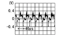
Check the signal between AV control unit connector and ground.
AV control unit
(-)
Condition
Reference value
(+)
Connector
Terminal
M104
52
Ground
Camera image is displayed
-
Is the inspection result normal?
YES >>Replace AV control unit. Refer to Removal and Installation.
NO >>Replace around view monitor control unit. Refer to Removal and Installation.
-
Other materials:
Operation
Switch Name and Function
Switch Name and Function
STEERING SWITCH
The steering switch is located on the steering
wheel.
Transmits the steering switch signal to the
combination meter.
...
Front Auxiliary Input Jacks
Diagnosis Procedure
Diagnosis Procedure
AUX JACK
CHECK AUX JACK HARNESS CONTINUITY
Ignition switch OFF.
Disconnect AV control unit connector and front
auxiliary input j ...
Handling Precaution
Precaution for Idle Start/stop System
Precaution for Idle Start/Stop System
PRECAUTIONS FOR IDLE START/STOP SYSTEM OPERATION
The operation of the idle start/stop system system needs to
satisfy various conditions. For details of the conditions, refer to System Description.
The idle start ...