Nissan Sentra Service Manual: B0092 Rear side air bag satellite sensor LH
Description
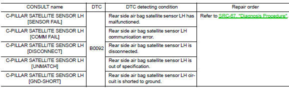
DTC B0092 REAR SATELLITE SENSOR LH
The rear side air bag satellite sensor LH is wired to the air bag diagnosis sensor unit. The air bag diagnosis sensor unit will monitor the rear side air bag satellite sensor LH for internal failures and its circuits for communication errors.
PART LOCATION
Refer to SRC-5, "Component Parts Location".
DTC Logic
DTC DETECTION LOGIC
With CONSULT
DTC CONFIRMATION PROCEDURE (With CONSULT)
1.CHECK SELF-DIAG RESULT
- Turn ignition switch ON.
- Check for DTC using CONSULT.
Is the DTC detected? YES (Current DTC)>>Refer to SRC-67, "Diagnosis Procedure".
YES (Past DTC)>>GO TO 2.
NO >> Inspection End.
2.ERASE SELF-DIAG RESULT
Erase the DTC using CONSULT.
Can the DTC be erased? YES >> Inspection End.
NO >> Refer to SRC-67, "Diagnosis Procedure".
DTC CONFIRMATION PROCEDURE (Without CONSULT)
1.CHECK SELF-DIAG RESULT
- Turn ignition switch ON.
- Check the air bag warning lamp status. Refer to SRC-17, "Trouble Diagnosis without CONSULT".
NOTE:
SRS will not enter diagnosis mode if no malfunction is detected in user mode.
Is the DTC detected? YES >> Refer to SRC-67, "Diagnosis Procedure".
NO >> Inspection End.
Diagnosis Procedure
1.HARNESS CONNECTOR
Visually inspect all applicable harness connectors for the following:
- Visible damage to connector or terminal
- Loose terminal
- Poor connection
NOTE:
All harness connectors should be inspected from the air bag diagnosis sensor unit to the end component (including any in-line connectors).
Is the inspection result normal? YES >> GO TO 2.
NO >> Perform one of the following repairs:
- Visible damage: Replace the harness.
- Loose terminal: Secure the terminal.
- Poor connection: Secure the connection.
2.CONFIRM DTC
- Reconnect all harness connectors.
- Turn ignition switch ON.
- Check for DTC using CONSULT.
Is DTC still current? YES >> GO TO 3.
NO >> Refer to GI-39, "Intermittent Incident".
3.WIRING HARNESS
Check the wiring harness for visible damage.
NOTE:
The entire wiring harness should be inspected from the air bag diagnosis sensor unit to the end component (including any in-line connectors).
Is the inspection result normal? YES >> GO TO 4.
NO >> Replace the harness.
4.CONFIRM DTC
- Reconnect all harness connectors.
- Turn ignition switch ON.
- Check for DTC using CONSULT.
Is DTC still current? YES >> GO TO 5.
NO >> Refer to GI-39, "Intermittent Incident".
5.REAR SIDE AIR BAG SATELLITE SENSOR LH
- Replace the rear side air bag satellite sensor LH. Refer to SR-26, "Removal and Installation".
- Turn ignition switch ON.
- Check for DTC using CONSULT.
Is DTC still current? YES >> GO TO 6.
NO >> Clear DTC. Inspection End.
6.AIR BAG DIAGNOSIS SENSOR UNIT
- Replace the air bag diagnosis sensor unit. Refer to SR-28, "Removal and Installation".
- Turn ignition switch ON.
- Check for DTC using CONSULT.
Is DTC still current? YES >> GO TO 7.
NO >> Clear DTC. Inspection End.
7.RELATED HARNESS
Replace the related harness.
>> END
 B0091 Front side air bag satellite sensor LH
Description
DTC B0091 FRONT SATELLITE SENSOR LH
The front side air bag satellite sensor LH is wired to the air bag diagnosis
sensor unit. The air bag diagnosis
sensor unit will monitor the front ...
 B0093 FRont door satellite sensor LH
Description
DTC B0093 FRONT DOOR SATELLITE SENSOR LH
The front door satellite sensor LH is wired to the air bag diagnosis sensor
unit. The air bag diagnosis sensor
unit will monitor the front do ...
Other materials:
Low tire pressure warning lamp
Symptom Table
Low tire pressure warning lamp symptom chart
Note:
If tire pressure sensor wake-up operation is not completed for two or more
tire pressure sensors, the applicable
low tire pressure warning lamp blinking patterns are displayed continuously.
(Example: blinks once/off/bl ...
Malfunction indicator lamp
Component Function Check
1.CHECK MIL FUNCTION
Turn ignition switch ON.
Check that MIL lights up.
Is the inspection result normal?
YES >> INSPECTION END
NO >> Proceed to EC-467, "Diagnosis Procedure".
Diagnosis Procedure
1.CHECK DTC WITH ECM
Check that DTC UXXXX i ...
Wiring diagram
Manual air conditioning system
Wiring Diagram
Manual heater system
Wiring Diagram
...
