Nissan Sentra B18 (2020-2025) Service Manual: Around View Monitor Control Unit
Values on the Diagnosis Tool

The following table includes information (items) inapplicable to this Nissan Sentra vehicle. For information (items) applicable to this vehicle, refer to CONSULT display items.
|
Monitor Item |
Condition |
Value/Status |
|---|---|---|
|
CAMERA OFF SIGNAL |
CAMERA switch ON. |
Off |
|
CAMERA switch OFF. |
On |
|
|
CAMERA SWITCH SIGNAL |
CAMERA switch OFF. |
Off |
|
CAMERA switch ON. |
On |
|
|
DR-SIDE CAMERA IMAGE SIG |
Side camera LH inoperative. |
NG |
|
Side camera LH operative. |
OK |
|
|
F-CAMERA IMAGE SIGNAL |
Front camera inoperative. |
NG |
|
Front camera operative. |
OK |
|
|
ILL |
Illumination OFF. |
Off |
|
Illumination ON. |
On |
|
|
PA-SIDE CAMERA IMAGE SIG |
Side camera RH inoperative. |
NG |
|
Side camera RH operative. |
OK |
|
|
REAR CAMERA IMAGE SIGNAL |
Rear view camera inoperative. |
NG |
|
Rear view camera operative. |
OK |
|
|
REVERSE SIGNAL |
When selector lever is in any position other than R (reverse). |
Off |
|
When selector lever in R (reverse). |
On |
|
|
ST ANGLE SENSOR SIGNAL |
Around view monitor control unit is not receiving steering angle sensor signal. |
Off |
|
Around view monitor control unit is receiving steering angle sensor signal. |
On |
|
|
ST ANGLE SENSOR TYPE |
Steering angle sensor type. |
Absolute |
|
STEERING GEAR RATIO TYPE |
Steering gear ratio type. |
Type 0 |
|
STEERING POSITION |
Left hand drive Nissan Sentra vehicle. |
LHD |
|
Right hand drive Nissan Sentra vehicle. |
RHD |
|
|
TURN SIGNAL |
Turn signal OFF. |
Off |
|
Turn signal ON. |
On |
|
|
Nissan Sentra Vehicle SPEED SIGNAL |
While driving, equivalent to speedometer reading |
mph, km/h |
Reference Value
TERMINAL LAYOUT

PHYSICAL VALUES
|
Terminal (Wire color) |
Description |
Condition |
Reference value (Approx.) |
||
|---|---|---|---|---|---|
|
+ |
– |
Signal name |
Input/Output |
||
|
1 (Shield) |
— |
Calibration connector (not used) |
— |
— |
— |
|
2 (B) |
— |
Calibration connector (not used) |
— |
— |
— |
|
3 (Shield) |
— |
Video output shield |
— |
— |
— |
|
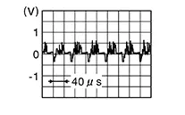
4 (W) |
Ground |
Video output signal |
Output |
[Ignition switch ON]
|
 |
|
5 (B) |
— |
Front camera ground |
— |
[Ignition switch ON] |
0 V |
|
6 (Y) |
5 (B) |
Front camera power supply |
Output |
[Ignition switch ON] |
6.0 V |
|
7 (Shield) |
— |
Front camera video ground |
— |
[Ignition switch ON] |
0 V |
|
8 (L) |
7 (Shield) |
Front camera video signal |
Input |
[Ignition switch ON]
|
|
|
9 (W) |
— |
Door mirror RH camera ground |
— |
[Ignition switch ON] |
0 V |
|
10 (R) |
9 (W) |
Door mirror RH camera power supply |
Output |
[Ignition switch ON] |
6.0 V |
|
11 (Shield) |
— |
Door mirror RH camera video ground |
— |
[Ignition switch ON] |
0 V |
|
12 (B) |
11 (Shield) |
Door mirror RH camera video signal |
Input |
[Ignition switch ON]
|
|
|
13 (R) |
— |
Door mirror LH camera ground |
— |
[Ignition switch ON] |
0 V |
|
14 (W) |
13 (R) |
Door mirror LH camera power supply |
Output |
[Ignition switch ON] |
6.0 V |
|
15 (Shield) |
— |
Door mirror LH camera video ground |
— |
[Ignition switch ON] |
0 V |
|
16 (B) |
15 (Shield) |
Door mirror LH camera video signal |
Input |
[Ignition switch ON]
|
|
|
17 (W) |
— |
Rear view camera ground |
— |
[Ignition switch ON] |
0 V |
|
18 (R) |
17 (W) |
Rear view camera power supply |
Output |
[Ignition switch ON] |
6.0 V |
|
19 (Shield) |
— |
Rear view camera video ground |
— |
[Ignition switch ON] |
0 V |
|
20 (B) |
19 (Shield) |
Rear view camera video signal |
Input |
[Ignition switch ON]
|
|
|
24 (LA/LG) |
— |
CAN-Low |
Input/Output |
— |
— |
|
26 (LA/GR) |
— |
CAN-High |
Input/Output |
— |
— |
|
28 (R) |
— |
Calibration connector (not used) |
— |
— |
— |
|
29 (BG) |
— |
Calibration connector (not used) |
— |
— |
— |
|
30 (P) |
— |
Calibration connector (not used) |
— |
— |
— |
|
39 (B) |
— |
Ground |
— |
[Ignition switch ON] |
0 V |
|
40 (LA/V) |
39 (B) |
Ignition signal |
Input |
[Ignition switch ON or START] |
Battery voltage |
Fail-Safe (around View Monitor Control Unit)
|
DTC Display contents of CONSULT |
Fail-safe condition |
|---|---|
|
B2A04-51: Calibration |
|
|
B2A05-55: Configuration |
|
|
B2A0B-86: Nissan Sentra Vehicle speed sensor |
|
|
B2A1A-38: Rear camera |
|
|
B2A1B-38: Side camera RH |
|
|
B2A1C-38: Front camera |
|
|
B2A1D-38: Side camera LH |
|
|
C1A39–00: STRG SEN CIR |
Predictive course line is not displayed. |
|
U1010–00: CONTROL UNIT(CAN) |
Intelligent around view monitor system is inoperative. |
|
U1232–00: ST ANGLE SEN CALIB |
Predictive course line is not displayed. |
|
U2141-87: CAN comm err (TCM) |
|
|
U2148-87: CAN comm err (brake control unit) |
The screen does not disappear even when the Nissan Sentra vehicle speed is 6.2 MPH (10 km/h) or more. MOD (Moving Object Detection) function does not operate. |
|
U214F-87: CAN comm err (BCM) |
|
|
U2154-87: CAN comm err (MIU) |
|
|
U215B-87: CAN comm err (IPDM E/R) |
— |
 display (red) is displayed (applicable
for unmatched camera only).
display (red) is displayed (applicable
for unmatched camera only). marking (Red) is displayed.
Dtc Inspection Priority Chart
If multiple DTCs are detected simultaneously, check them one by one depending on the following DTC inspection priority chart:
|
Priority |
Detected items (DTC) |
|---|---|
|
1 |
|
|
2 |
|
|
3 |
|
Dtc Index
|
DTC |
CONSULT display |
Refer to |
|---|---|---|
|
B2A04–51 |
Calibration |
DTC Description |
|
B2A05–55 |
Configuration |
DTC Description |
|
B2A0B–86 |
Nissan Sentra Vehicle speed sensor |
DTC Description |
|
B2A1A–38 |
Rear camera |
DTC Description |
|
B2A1B–38 |
Side camera RH |
DTC Description |
|
B2A1C–38 |
Front camera |
DTC Description |
|
B2A1D–38 |
Side camera LH |
DTC Description |
|
C1A39–00 |
STRG SEN CIR |
DTC Description |
|
U1010–00 |
CONTROL UNIT(CAN) |
DTC Description |
|
U1232–00 |
ST ANGLE SEN CALIB |
DTC Description |
|
U2141–87 |
CAN comm err (TCM) |
DTC Description |
|
U2148–87 |
CAN comm err (brake control unit) |
DTC Description |
|
U214F–87 |
CAN comm err (BCM) |
DTC Description |
|
U2154–87 |
CAN comm err (MIU) |
DTC Description |
|
U215B–87 |
CAN comm err (IPDM E/R) |
DTC Description |
 Av Control Unit
List of Ecu Reference
List of ECU Reference
ECU
Reference
A ...
Other materials:
Dtc Confirmation Procedure
DTC Confirmation
Procedure
PERFORM SELF DIAGNOSTIC RESULT
CONSULT
Ignition switch ON.
CAUTION:
Never start the engine.
...
Driver Assistance Buzzer
Removal and Installation
Removal and
Installation
REMOVAL
Remove left knee air bag module.
Refer to Removal and Installation.
Remove steering column covers. Refer
to Removal and Installation.
Remove screw (A) from driver assistance
buzzer (1).
Disconnect harness co ...
Front Disc Brake
Inspection - Front Brake Pad
Inspection - Front Brake Pad
INSPECTION
Check brake pad wear thickness from an
inspection hole (A) on cylinder body.
Wear thickness
: Refer to Front Disc Brake.
...
