Nissan Sentra Service Manual: Wiring diagram
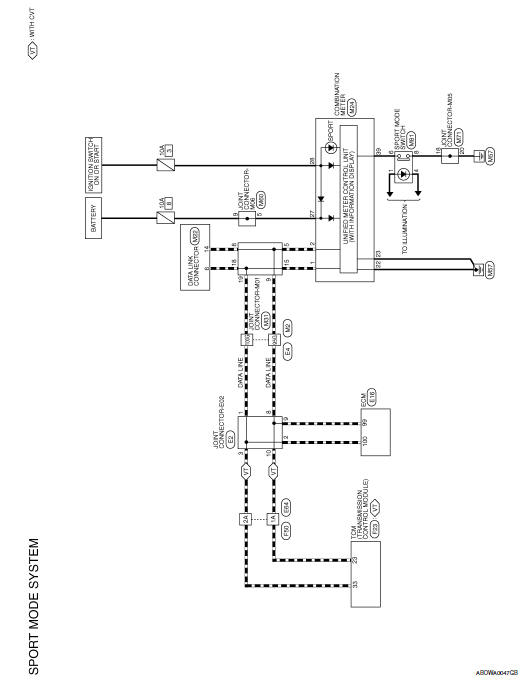
Sport mode system
Wiring diagram

 Ecu diagnosis information
Sport mode
List of ecu reference
...
 Basic inspection
Diagnosis and repair work flow
Work flow
Detailed flow
1.Obtain information about symptom
Interview the customer to obtain as much information as possible about the
conditions and environment un ...
Other materials:
Primary speed sensor
Exploded View
Transaxle assembly
O-ring
Primary speed sensor
: Always replace after every
disassembly.
: N m (kg-m, in-lb)
: Genuine NISSAN CVT Fluid NS-3
Removal and Installation
REMOVAL
Disconnect the primary speed sensor connector.
Remove the primary speed sensor.
...
Compass display (if so equipped)
This unit measures terrestrial magnetism and indicates
heading direction of vehicle.
With the ignition switch in the ON position, press
the button as described in the
chart below
to activate various features of the automatic antiglare
rearview mirror.
For more information about the au ...
Precaution
Precaution for supplemental restraint system (srs) "air bag" and "seat belt
pre-tensioner"
The supplemental restraint system such as “air bag” and “seat belt pre-tensioner”,
used along
with a front seat belt, helps to reduce the risk or severity of injur ...
