Nissan Sentra Owners Manual: Compass display (if so equipped)
This unit measures terrestrial magnetism and indicates heading direction of vehicle.
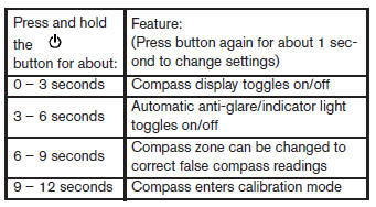
With the ignition switch in the ON position, press
the  button as described in the
chart below
to activate various features of the automatic antiglare
rearview mirror.
For more information about the automatic antiglare feature, refer to “Automatic anti-glare rearview mirror” in the “Pre-driving checks and adjustments” section.
Compass display
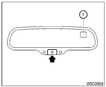
Push the  button for about 1
second when
the ignition switch is placed in the ON position to
toggle the compass direction display 1 on or
off. The display will indicate the direction that the
vehicle is heading.
N: North
E: East
S: South
W: West
If the display reads “C”, calibrate the compass by driving the vehicle in three complete circles at less than 5 MPH (8 km/h).
You can also calibrate the compass by driving your vehicle on your everyday route. The compass will be calibrated once it has tracked three complete circles.
Zone variation change procedure
The difference between magnetic north and geographical north is known as variance. In some areas, this difference can sometimes be great enough to cause false compass readings. Follow these instructions to set the variance for your particular location if this happens:
- Press and hold the
 button
for about 11 seconds. The current zone number will appear in the display. Release the button. - Find your current location on the zone map.
Refer to the illustration.
- Press the
 button repeatedly
to toggle through the zone numbers until the desired number appears in the display. Once you have selected a zone number, the display will show a compass direction within a few seconds.
Inaccurate compass direction:
The compass display is equipped with automatic correction function. If the correct direction is not shown, follow this procedure.
- With the display turned on, press and hold the button for about 13 seconds. The “C” icon in the compass display will illumi- nate.
- Calibrate the compass by driving the vehicle in three complete circles at a maximum speed of 5 MPH (8 km/h).
- After completing the circles, the display should return to normal.
CAUTION
- Do not install a ski rack, antenna, etc., which are attached to the vehicle by means of a magnet. They affect the operation of the compass.
- When cleaning the mirror, use a paper towel or similar material dampened with glass cleaner. Do not spray glass cleaner directly on the mirror as it may cause the liquid cleaner to enter the mirror housing.
 Outside temperature display
The outside temperature function provides a display
of the outside temperature when the ignition
switch is placed in the ON position.
The display of positive temperatures is unsigned
(blank), ne ...
 Warning/indicator lights and audible reminders
Anti-lock Braking System (ABS)
warning light
Brake warning light
Charge warning light
Door open warning light
Engine oil pressure warning
light
Low fuel warning light
Low tire pressure ...
Other materials:
Service data and specifications
(sds)
General Specification
Drive Belt
Spark Plug
*:Always check with the Parts Department for the latest parts information.
Exhaust Manifold
Camshaft
VALVE LIFTER
VALVE CLEARANCE
*: Approximately 80В°C (176В°F)
AVAILABLE VALVE LIFTER
*:Always check with the P ...
Component parts
Component Parts Location
Driver air bag module
Front passenger air bag off indicator
Front passenger air bag module
Front LH side air bag module
(RH similar)
LH side curtain air bag module
(view with headliner removed)
(RH similar)
Front LH seatbelt pre-tensioner
(view wit ...
Antenna
Window antenna
The antenna pattern is printed inside the rear
window.
CAUTION
Do not place metalized film near the
rear window glass or attach any metal
parts to it. This may cause poor reception
or noise.
When cleaning the inside of the rear
window, be careful not to scratch or
d ...
