Nissan Sentra Service Manual: Water hose
Exploded View
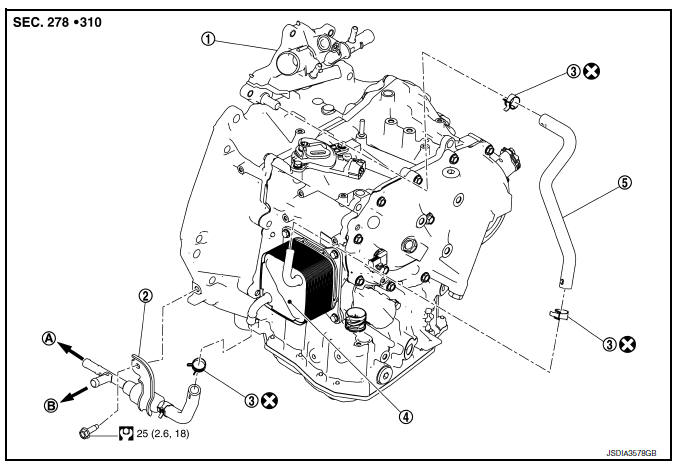
- Water outlet
- Heater thermostat assembly
- Hose clamp
- CVT oil warmer
- Water hose
- To thermostat housing
- To engine oil cooler
 : Always replace after every
disassembly.
 : NВ·m (kg-m, ft-lb)
Removal and Installation
REMOVAL
WARNING:
Do not remove the radiator cap when the engine is hot. Serious burns could occur from high-pressure coolant escaping from the radiator. Wrap a thick cloth around the cap. Slowly push down and turn it a quarter turn to allow built-up pressure to escape. Carefully remove the cap by pushing it down and turning it all the way.
CAUTION:
Perform these steps after the coolant temperature has cooled sufficiently.
NOTE:
When removing components such as hoses, tubes/lines, etc., cap or plug openings to prevent fluid from spilling.
- Remove the engine under cover. Refer to EXT-31, "ENGINE UNDER COVER : Removal and Installation".
- Drain engine coolant from radiator. Refer to CO-12, "Changing Engine Coolant".
- Remove water hose and heater thermostat assembly.
INSTALLATION
Installation is in the reverse order of removal.
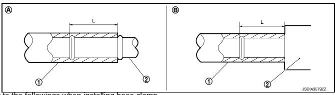
- Refer to the following when installing water hoses.
| Water hose (1) | Installation side tube (2) | Direction of paint mark | Hose insertion depth (L) |
| Heater thermostat assembly | CVT oil warmer | Frontward | (A): 27 mm (1.06 in) (Hose end reaches the 2-stage bulge.) |
| Water hose | CVT oil warmer | Frontward | |
| Water outlet | Frontward | B): 27 mm (1.06 in) (Hose end reaches the end of water outlet tube.) |
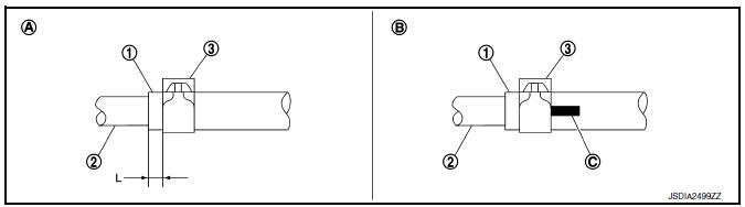
- Refer to the followings when installing hose clamp.
CAUTION:
- Do not reuse hose clamp.
- Hose clamp should not interfere with the bulge of fluid cooler tube.
| Water hose (1) | Installation side tube (2) | Hose clamp (3) | |
| Direction of tab | Clamping position | ||
| Heater thermostat assembly | CVT oil warmer | Frontward | (B): Align with the end of paint mark (C) |
| Water hose | CVT oil warmer | Frontward | (A): 5 – 7 mm (0.20 – 0.28 in) (L) from hose end |
| Water outlet | Frontward | ||
Inspection
INSPECTION AFTER REMOVAL
Heater Thermostat
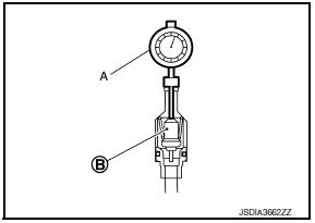
- Fully immerse the heater thermostat 1 in a container (A) filled with water. Continue heating the water while stirring.
- Continue heating the heater thermostat for 5 minutes or more after bringing the water to a boil.
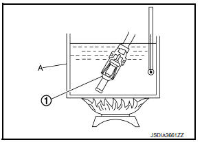
- Quickly take the heater thermostat out of the hot water, measure the heater thermostat within 10 seconds.
- Place dial indicator (A) on the pellet (B) and measure the elongation from the initial state.
Standard : Refer to TM-289, "Heater Thermostat".
- If out of standard, replace heater thermostat.
INSPECTION AFTER INSTALLATION
Start the engine, and check the joints for coolant leakage.
 Differential side oil seal
Exploded View
Transaxle assembly
Differential side oil seal (left side)
Differential side oil seal (right side)
: Vehicle front
: Always replace after every
disassembly.
: Genuin ...
 Plug
Plug
Description
Replace the O-ring if oil leakage or exudes from the plug.
Exploded View
Plug
O-ring
O-ring
Plug
: Always replace after every
disassembly.
: NВ·m (kg-m, ft-lb)
...
Other materials:
P2118 Throttle control motor
DTC Logic
DTC DETECTION LOGIC
DTC No.
CONSULT screen terms
(Trouble diagnosis content)
DTC detecting condition
Possible cause
P2118
ETC MOT-B1
(Throttle actuator control
motor current range/
performance)
ECM detects short in both circuits between
ECM a ...
Rear seat belt
Exploded View - Seat Belt Retractor
Seat belt retractor (RH)
Seat belt retractor (center)
Seat belt retractor (LH)
Front
Removal and Installation - Seat Belt Retractor
REMOVAL
Remove the rear parcel shelf finisher. Refer to INT-33, "Removal and
Installation".
Re ...
Wiring diagram
Navigation with bose
Wiring diagram
...
