Nissan Sentra Service Manual: Vacuum lines
Exploded View
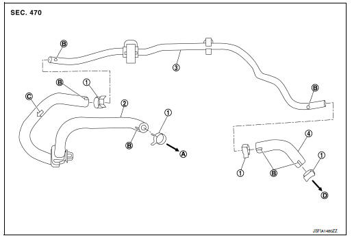
- Clamp
- Vacuum hose (built-in check valve)
- Vacuum piping
- Vacuum hose
- To intake manifold side
- Paint mark
- Stamp indicating engine direction
- To brake booster
Removal and Installation
REMOVAL
- Remove air duct and air cleaner case. Refer to EM-25, "Removal and Installation".
- Remove the vacuum hoses and vacuum piping.
INSPECTION AFTER REMOVAL
Visual Inspection
Check for correct installation, damage and deterioration of the vacuum hoses and pipe.
Valve Air-tightness Check
- Connect a suitable tool at each end of the vacuum hose with built-in check valve to inspect the check valve operation.
Vacuum applied at booster end : Refer to BR-54, "Check Valve".
Vacuum applied at intake manifold end : Refer to BR-54, "Check Valve".
- Replace the vacuum hose with built-in check valve if out of specification.
INSTALLATION
Installation is in the reverse order of removal.
- When installing vacuum hose, insert it until its tip reaches the back-end of length (A) or further as shown.
CAUTION:
Do not use lubricating oil during assembly
Length (A) : 24 mm (0.95 in) or more
- Face the paint mark of vacuum hose (build-in check valve) (intake manifold side) to vehicle right side to assemble.
- Face the paint mark of vacuum hose (build-in check valve) (brake booster side) to vehicle front side to assemble.
- Face the paint mark of vacuum piping (intake manifold side) to vehicle front side to assemble.
- Face the paint mark of vacuum piping (brake booster side) to downward to assemble.
- Face the paint mark of vacuum hose (intake manifold side) to downward to assemble.
- Face the paint mark of vacuum hose (brake booster side) to vehicle front side to assemble.
- For clamp mounting direction (the orientation of pawl), refer to BR-36, "Exploded View".
 Brake booster
Exploded View
Master cylinder assembly
Brake booster
Lock nut
Clevis
Gasket
Spacer
Removal and installation
REMOVAL
Remove cowl top and cowl top extension. Refer to EXT-26, ...
 Front disc brake
BRAKE PAD
BRAKE PAD : Exploded View
Cylinder body
Inner shim cover
Inner shim
Inner pad (with pad wear sensor)
Pad retainer
Torque member
Outer pad
Outer shim
Outer shim cover ...
Other materials:
Rear power window switch
Removal and Installation
REMOVAL
Release the pawls using a suitable tool and lift the rear power window
switch and finisher as an assembly
and remove
Disconnect the harness connector from the rear power window switch.
Release the pawl (one on each side) using a suitable tool, then
se ...
Abs actuator and electric unit (control unit)
Exploded View
ABS actuator and electric unit (control
unit)
ABS actuator and electric unit (control
unit) harness connector
Bushing
Bracket
To master cylinder secondary side
To master cylinder primary side
To rear LH caliper
To front RH caliper
...
Trunk room trim
Exploded View
Trunk floor trim
Trunk front floor spacer (LH)
Trunk side finisher (LH)
Reflector box assembly*
Trunk rear plate
Trunk side finisher (RH)
Trunk front floor spacer (RH)
Clip
Pawl
Trunk rear plate
TRUNK REAR PLATE : Removal and Installation
REMOVAL
Remove ...
