Nissan Sentra Service Manual: Front disc brake
BRAKE PAD
BRAKE PAD : Exploded View
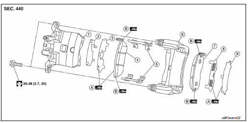
- Cylinder body
- Inner shim cover
- Inner shim
- Inner pad (with pad wear sensor)
- Pad retainer
- Torque member
- Outer pad
- Outer shim
- Outer shim cover
- Molykote AS880N
- Molykote 7439
BRAKE PAD : Removal and Installation
REMOVAL
WARNING:
Clean dust on brake caliper and brake pad with a vacuum dust collector to minimize the hazards of airborne particles or other material.
CAUTION:
- Do not depress the brake pedal while removing the brake pads because the pistons may pop out.
- It is not necessary to remove bolts on torque member and brake hose except for disassembly or replacement of brake caliper. For brake pad removal, hang brake caliper with a wire so as not to stretch brake hose.
- If brake fluid or grease adheres to the brake caliper or disc rotor, quickly wipe it off.
- Partially drain brake fluid from the master cylinder. Refer to BR-17, "Drain and Refill".
- Remove front wheels and tires using power tool. Refer to WT-47, "Removal and Installation".
- Remove sliding pin bolts.
- Remove the brake caliper from the torque member. Leaving brake hose attached, reposition the brake caliper aside with wire.
- Remove the brake pads, shims, shim covers and pad retainers from the torque member.
CAUTION:
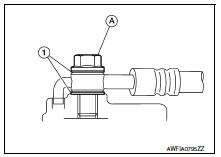
- Do not deform the pad retainer (2) when removing the pad retainer from the torque member (1).
- Do not damage the piston boot.
- Do not drop the brake pads, shims, and the shim covers.
- Note the position of components during removal to aid with installation.
INSTALLATION
- Install the pad retainers (1) to the torque member (2) if the pad retainers have been removed.
CAUTION:
- Do not deform brake pad retainers.
- Verify pad retainers are secured properly to torque member.
- Apply Molykote AS880N or equivalent to the mating faces (A) between the inner pad (1) and the inner shim (2), and install the inner shim and inner shim cover (3) to the inner pad.
CAUTION:
Always replace the shim and shim cover when replacing the brake pad.
- Apply Molykote AS880N or silicone-based grease to the mating faces (A) between the outer shim (1) and the outer shim cover (2), and install the outer shim and outer shim cover to the outer pad (3).
CAUTION:
Always replace the shim and shim cover when replacing the brake pad.
- Apply Molykote 7439 or equivalent to the mating faces (A) between the brake pads (1) and the pad retainers.
- Install the brake pads to the torque member.
CAUTION:
- Both inner and outer pads have a pad return system on the pad retainer. Install pad return lever (1) securely to pad retainer (2).
- Do not deform the pad retainers.
- Using a suitable tool, press piston into the brake caliper.
CAUTION:
Do not damage the piston boot.
- Install cylinder body to torque member.
- Install the sliding pin bolts and tighten them to specified torque.
- Depress the brake pedal several times to verify that drag does not exist.
- Install front wheels and tires. Refer to WT-47, "Removal and Installation".
Brake caliper assembly
BRAKE CALIPER ASSEMBLY : Exploded View

- Brake caliper assembly
BRAKE CALIPER ASSEMBLY : Removal and Installation
REMOVAL
WARNING:
Clean dust on brake caliper and brake pad with a vacuum dust collector to minimize the hazard of airborne particles or other materials.
CAUTION:
- Do not depress the brake pedal.
- Do not spill or splash brake fluid on painted surfaces. Brake fluid may damage paint. If brake fluid is splashed on painted areas, wash it away with water immediately.
- Do not bend, twist or pull the brake hoses and piping.
- Do not reuse drained brake fluid.
NOTE:
When removing components such as hoses, tubes/lines, etc., cap or plug openings to prevent fluid from spilling.
- Remove front wheels and tires using power tool. Refer to WT-47, "Removal and Installation".
- Secure the disc rotor using wheel nuts.
- Remove union bolt, copper sealing washers, and disconnect brake hose from brake caliper. Discard the copper sealing washers.
CAUTION:
Do not reuse copper sealing washers.
- Remove sliding pin bolts and the brake caliper.
CAUTION:
Do not drop brake pads or caliper.
INSTALLATION
- Position the brake caliper to torque member and install the sliding pin bolts. Tighten to specification.
- Assemble the union bolt (A) and the copper sealing washers (1)
to the brake hose and install it as an assembly to the brake caliper.
Align the brake hose L-pin by aligning it with the brake caliper hole, and tighten the union bolt (A) to the specified torque.
CAUTION:
Do not reuse copper sealing washers.
- Refill with new brake fluid and perform the air bleeding. Refer to BR-17, "Bleeding Brake System".
CAUTION:
- Do not reuse drained brake fluid.
- Do not spill or splash brake fluid on the disc rotor.
- Check the front disc brakes for drag. If drag exists, refer to BR- 12, "BRAKE PAD : Inspection".
- Install the front wheels and tires. Refer to WT-47, "Removal and Installation".
 Vacuum lines
Exploded View
Clamp
Vacuum hose (built-in check valve)
Vacuum piping
Vacuum hose
To intake manifold side
Paint mark
Stamp indicating engine direction
To brake booster
Remo ...
 Rear drum brake
BRAKE CALIPER ASSEMBLY : Exploded View
Shoe hold pin
Back plate
Plug
Brake shoe
Spring
Upper spring
Adjuster
Return spring
Brake drum
Boot
Piston
Piston cup
Spring
W ...
Other materials:
P0447 EVAP Canister vent control valve
DTC Logic
DTC DETECTION LOGIC
DTC No.
CONSULT screen terms
(Trouble diagnosis content)
DTC detecting condition
Possible cause
P0447
VENT CONTROL VALVE
(Evaporative emission system vent
control circuit open)
An improper voltage signal is sent to
ECM throug ...
Precaution
Precaution for supplemental restraint system (srs) "air bag" and "seat
belt pre-tensioner"
The Supplemental Restraint System such as ą▓ąéčÜAIR BAGą▓ąéč£ and ą▓ąéčÜSEAT BELT PRE-TENSIONERą▓ąéč£,
used along
with a front seat belt, helps to reduce the risk or severity of injur ...
Locking with power door lock switch
Door lock switch
To lock all the doors without a key, push the door
lock switch (driverŌĆÖs or front passengerŌĆÖs side) to
the lock position 1 . When locking the door this
way, be certain not to leave the key inside the
vehicle.
To unlock all the doors without a key, push the
door lock ...
