Nissan Sentra Service Manual: System description
DESCRIPTION
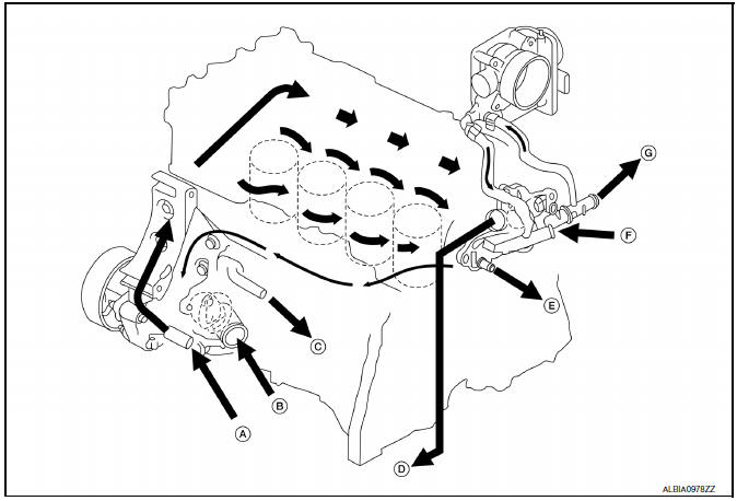
Engine Cooling System Schematic
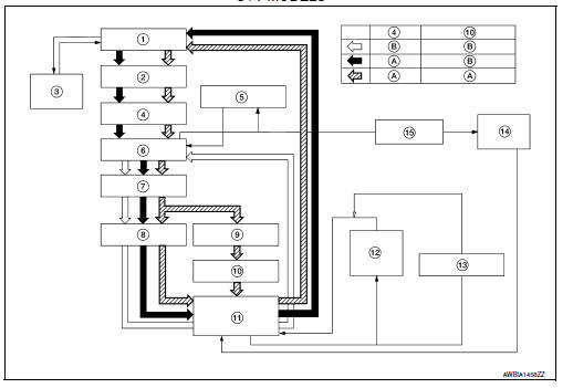
CVT Models
- Radiator
- Water inlet
- Reservoir tank
- Thermostat
- Engine oil cooler
- Thermostat housing
- Water pump
- Cylinder head
- Cylinder block
- Water control valve
- Water outlet
- Heater
- Electric throttle control actuator
- CVT oil warmer
- Heater thermostat
- Open
- Closed
CVT models
- From heater thermostat
- From radiator
- To engine oil cooler
- To engine oil cooler
- To CVT oil warmer
- From heater core
- To heater core
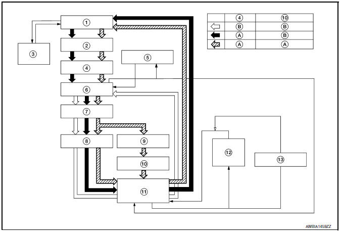
M/T Models
- Radiator
- Water inlet
- Reservoir tank
- Thermostat
- Engine oil cooler
- Thermostat housing
- Water pump
- Cylinder head
- Cylinder block
- Water control valve
- Water outlet
- Heater
- Electric throttle control actuator
- Open
- Closed
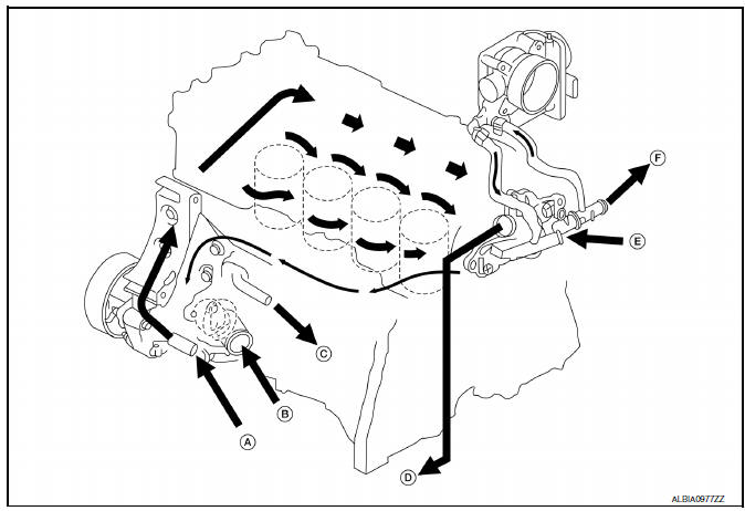
- From heater thermostat
- From radiator
- To engine oil cooler
- To filler neck
- From heater core
- To heater core
 Preparation
Special Service Tool
The actual shape of the tools may differ from those illustrated here.
Commercial Service Tool
...
 Symptom diagnosis
OVERHEATING CAUSE ANALYSIS
Troubleshooting Chart
Symptom
Check items
Cooling system
parts
malfunction
Poor heat transfer
Water pump malfunction
Worn or lo ...
Other materials:
Interior trunk lid release
WARNINGClosely supervise children when they are
around cars to prevent them from playing
and becoming locked in the trunk where
they could be seriously injured. Keep the
car locked, with the rear seatback and
trunk lid securely latched when not in use,
and prevent childr ...
Precaution for Brake System
WARNING:
Clean any dust from the front brake and rear brake with a vacuum
dust collector. Do not blow with
compressed air.
Brake fluid: Refer to MA-11, "Fluids and Lubricants".
Do not reuse drained brake fluid.
Do not spill or splash brake fluid on painted surfaces. Brake fluid ...
P0196 EOT Sensor
DTC Logic
DTC DETECTION LOGIC
NOTE:
If DTC P0196 is displayed with DTC P0197 or P0198, first perform the
trouble diagnosis for DTC P0197 or
P0198. Refer to EC-264, "DTC Logic".
DTC No.
CONSULT screen terms
(Trouble diagnosis content)
DTC detecting condition
Possib ...
