Nissan Sentra Service Manual: System description
Component parts
Component parts location
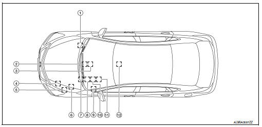
- ABS actuator and electric unit (control unit)
- Av control unit
- A/c auto amp.
- Ecm
- Ipdm e/r
- Tcm
- Data link connector
- EPS control unit
- Bcm
- Combination meter
- Steering angle sensor
- Air bag diagnosis sensor unit
System
Can communication system
Can communication system : system description
System diagram
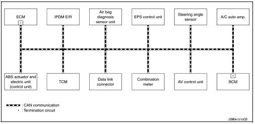
Description
Can (controller area network) is a serial communication line for real time application. It is an on-vehicle multiplex communication line with high data communication speed and excellent error detection ability. Many electronic control units are equipped onto a vehicle, and each control unit shares information and links with other control units during operation (not independent). In can communication, control units are connected with 2 communication lines (can-h line, can-l line) allowing a high rate of information transmission with less wiring.
Each control unit transmits/receives data but selectively reads required data only.
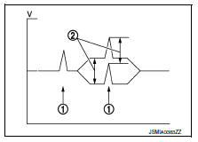
Can communication signal generation
- Termination circuits (resistors) are connected across the can communication system. When transmitting a can communication signal, each control unit passes a current to the can-h line and the current returns to the can-l line.
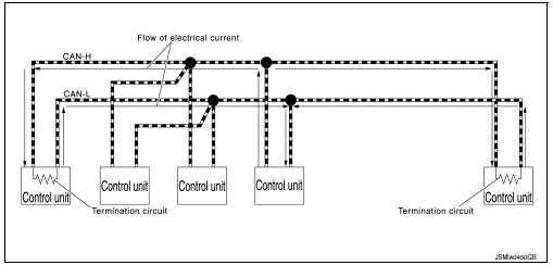
- The current flows separately into the termination circuits connected across the can communication system and the termination circuits drop voltage to generate a potential difference between the can-h line and the can-l line.
Note:
A signal with no current passage is called “recessive” and one with current passage is called “dominant”.
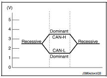
- The system produces digital signals for signal communications, by using the potential difference.
The construction of can communication signal (message)
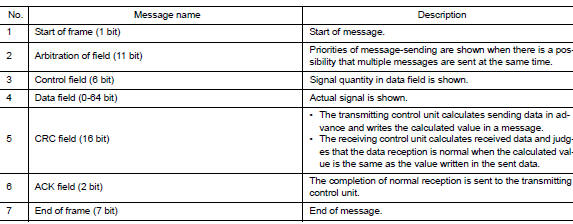
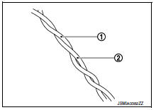
Can communication line
The can communication line is a twisted pair wire consisting of strands of can-h (1) and can-l (2) and has noise immunity.
Note:
The can communication system has the characteristics of noise-resistant because this system produces digital signals by using the potential difference between the can-h line and the can-l line and has the twisted pair wire structure.
Since the can-h line and the can-l line are always adjacent to each other, the same degree of noise occurs, respectively, when a noise (1) occurs. Although the noise changes the voltage, the potential difference (2) between the can-h line and the can-l line is insensitive to noise. Therefore, noise-resistant signals can be obtained.
Can signal communications
Each control unit of the can communication system transmits signals through the can communication control circuit included in the control unit and receives only necessary signals from each control unit to perform various kinds of control.
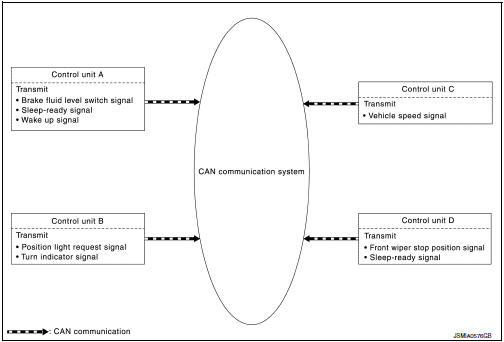
- Example: transmitted signals
- Example: received signals
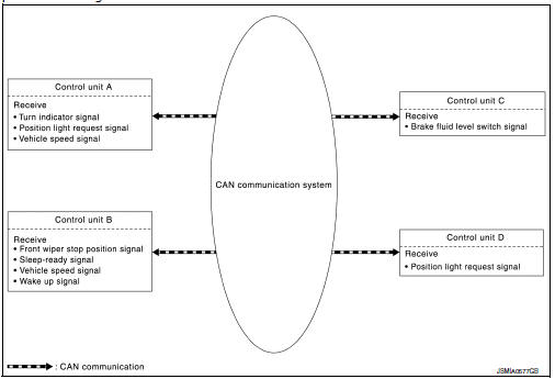
Note:
The above signal names and signal communications are provided for reference purposes. For can communications signals of this vehicle, refer to lan-30, "can communication system : can communication signal chart".
Can communication system : can communication control circuit
Can communication control circuit is incorporated into the control unit and transmits/receives can communication signals.
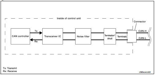
| Component | System description |
| Can controller | It controls can communication signal transmission and reception, error detection, etc. |
| Transceiver ic | It converts digital signal into CAN communication signal, and CAN communication signal into digital signal. |
| Noise filter | It eliminates noise of can communication signal. |
Termination circuit*
(resistance of approx. 120  ) ) |
Generates a potential difference between CAN-H and CAN-L. |
*: These are the only control units wired with both ends of CAN communication system.
Can communication system : can system specification chart
Determine CAN system type from the following specification chart.
Note:
Refer to lan-16, "trouble diagnosis procedure" for how to use can system specification chart.
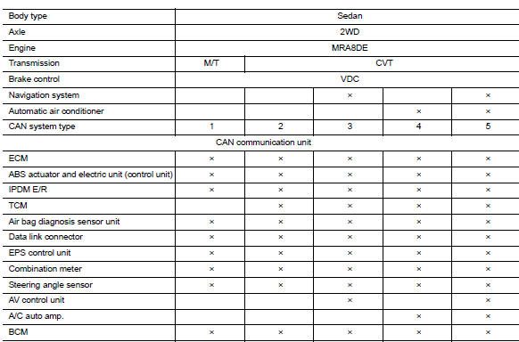
×: applicable
Vehicle equipment identification information
Note:
Check CAN system type from the vehicle shape and equipment.
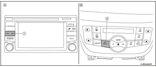
- Navi switch
- Automatic temperature control switch
- With navigation system
- With automatic air conditioner
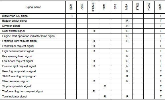
Can communication system : can communication signal chart
Refer to lan-15, "how to use can communication signal chart" for how to use can communication signal chart.
Note:
- Refer to lan-21, "abbreviation list" for the abbreviations of the connecting units.
- Can data of the air bag diagnosis sensor unit is not used by usual service work, thus it is omitted.
- The av control unit uses can communication only for communicating with the diagnostic tool (not with other connected control units).
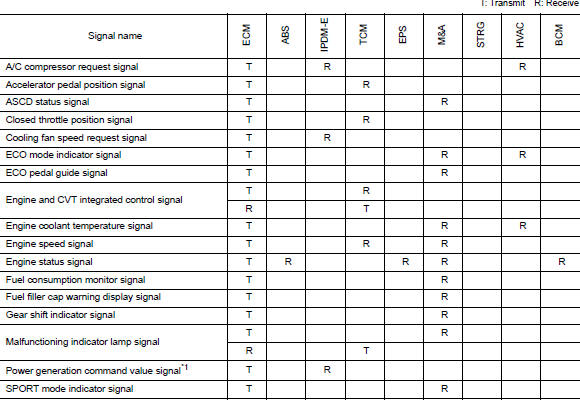
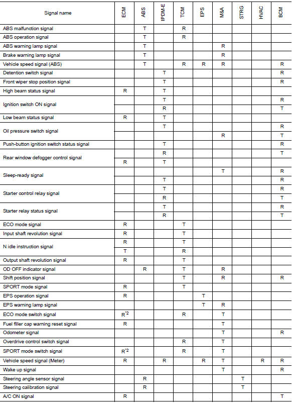
*1: With battery current sensor (with battery temperature sensor)
*2: M/t models
 Precaution
Precaution for supplemental restraint system (srs) "air bag" and "seat
belt pre-tensioner"
The Supplemental Restraint System such as “AIR BAG” and “SEAT BELT PRE- ...
 Wiring diagram
Can system
Wiring Diagram
...
Other materials:
Automatic speed control device (ASCD)
AUTOMATIC SPEED CONTROL DEVICE (ASCD) : System Description
SYSTEM DIAGRAM
BASIC ASCD SYSTEM
Refer to Owner's Manual for ASCD operating instructions.
Automatic Speed Control Device (ASCD) allows a driver to keep vehicle at
predetermined constant speed
without depressing accelerator pedal ...
Diagnosis description : system readiness
test (SRT) code
System Readiness Test (SRT) code is specified in Service $01 of SAE J1979/ISO
15031-5.
As part of an enhanced emissions test for Inspection & Maintenance (I/M),
certain states require the status of
SRT be used to indicate whether the ECM has completed self-diagnosis of major
emission s ...
Precaution
Precaution for Supplemental Restraint System (SRS)
"AIR BAG" and "SEAT BELT PRE-TENSIONER"
The Supplemental Restraint System such as “AIR BAG” and “SEAT BELT PRE-TENSIONER”,
used along
with a front seat belt, helps to reduce the risk or severity of injur ...
