Nissan Sentra Service Manual: System
STARTING SYSTEM (WITH INTELLIGENT KEY)
Component Parts Location
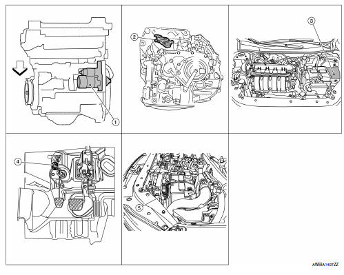
- Starter motor
- Transmission range switch (CVT Models)
- IPDM E/R (view with air inlet duct removed)
- Clutch interlock switch (M/T Models)
- ECM
Component Description
| Component part | Description |
| Starter motor | The starter motor plunger closes and the motor is supplied with battery power, which in turn cranks the engine, when the S terminal is supplied with electric power. |
| Transmission range switch | Supplies power to the starter relay and starter control relay (inside IPDM E/R) when the selector lever is shifted into the P or N position. |
| IPDM E/R | CPU inside IPDM E/R operates the starter relay when the ignition switch is in the start position. |
| Clutch interlock switch (M/T Models) | Clutch interlock switch supplies power to the coil side of the starter when the clutch pedal is depressed to crank the engine. |
| ECM | ECM controls the starter relay inside the IPDM E/R. |
STARTING SYSTEM (WITHOUT INTELLIGENT KEY)
System Diagram
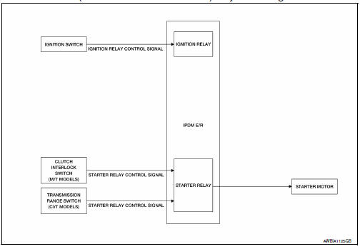
System Description
The starter motor plunger closes and provides a closed circuit between the battery and the starter motor. The starter motor is grounded to the cylinder block. With power and ground supplied, the starter motor operates.
STARTING SYSTEM (WITHOUT INTELLIGENT KEY)
STARTING SYSTEM (WITHOUT INTELLIGENT KEY) : System Diagram
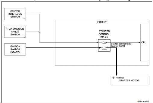
*1: M/T models
*2: CVT models
STARTING SYSTEM (WITHOUT INTELLIGENT KEY) : System Description
CVT MODELS
- When the selector lever is in the P or N position, power is supplied to starter control relay by the transmission range switch. The IPDM E/R (CPU) detects selector lever P/N condition by the inputted signal.
- When engine cranking condition is satisfied, then battery power is supplied to starter motor (“S” terminal) through starter control relay.
M/T MODELS
When the clutch pedal is depressed, battery power is supplied to starter motor (“S” terminal).
 Component parts
STARTING SYSTEM (WITH INTELLIGENT KEY)
Component Parts Location
Starter motor
Transmission range switch (CVT Models)
IPDM E/R (view with air inlet duct
removed)
Clutch interlock switc ...
 Wiring diagram
...
Other materials:
Parking brake switch signal circuit
Component function check
1.Check parking brake switch operation
Check that brake warning lamp in combination meter turns on/off when parking
brake is actuated.
Is the inspection result normal?
Yes >> inspection end.
No >> proceed to diagnosis procedure. Refer to mwi-60, " ...
System
VDC/TCS/ABS
VDC/TCS/ABS : System Diagram
VDC/TCS/ABS : System Description
The system switches fluid pressure of each brake caliper and
each wheel cylinder to increase, to hold, or to
decrease according to signals from control unit in ABS actuator and electric
unit (control unit) ...
Front fog lamp circuit
Description
The ipdm e/r (intelligent power distribution module engine room) controls the
front fog lamp relay based on
inputs from the bcm over the can communication lines. When the front fog lamp
relay is energized, power
flows from the front fog lamp relay in the ipdm e/r to the front fog ...
