Nissan Sentra Service Manual: Component parts
STARTING SYSTEM (WITH INTELLIGENT KEY)
Component Parts Location
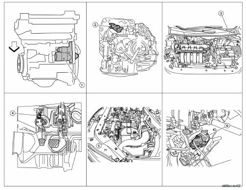
- Starter motor
- Transmission range switch (CVT Models)
- IPDM E/R (view with air inlet duct removed)
- Clutch interlock switch (M/T Models)
- ECM
- BCM (view under instrument panel, left side of vehicle)
Component Description
| Component part | Description |
| Starter motor | The starter motor plunger closes and the motor is supplied with battery power, which in turn cranks the engine, when the S terminal is supplied with electric power. |
| Transmission range switch (CVT Models) | Transmission range switch supplies power to the starter relay and starter control relay inside the IPDM E/R when the shift selector is placed in the P or N position. |
| IPDM E/R | CPU inside IPDM E/R operates the starter relay when the ignition switch is in the start position. |
| Clutch interlock switch (M/T Models) | Clutch interlock switch supplies power to the coil side of the starter when the clutch pedal is depressed to crank the engine. |
| ECM | ECM controls the starter control relay inside the IPDM E/R. |
| BCM | BCM controls the starter relay inside IPDM E/R. |

 System
STARTING SYSTEM (WITH INTELLIGENT KEY)
Component Parts Location
Starter motor
Transmission range switch (CVT Models)
IPDM E/R (view with air inlet duct
removed)
Clutch interlock switc ...
Other materials:
Diagnosis system [abs actuator and electric unit (control
unit)]
CONSULT Function (ABS)
FUNCTION
CONSULT can display each diagnostic item using the following
direct diagnostic modes.
Direct Diagnostic Mode
Description
ECU identification
The ABS actuator and electric unit (control unit) part number is
displayed.
Self Diagnos ...
Eco mode control
ECO MODE CONTROL : System Description
SYSTEM DIAGRAM
SYSTEM DESCRIPTION
ECM receives an ECO mode signal from combination meter via CAN
communication and improves the fuel
economy by controlling the throttle movement to less than usual. Therefore,
driving characteristic is controlle ...
Diagnosis description : system readiness
test (SRT) code
System Readiness Test (SRT) code is specified in Service $01 of SAE J1979/ISO
15031-5.
As part of an enhanced emissions test for Inspection & Maintenance (I/M),
certain states require the status of
SRT be used to indicate whether the ECM has completed self-diagnosis of major
emission s ...
