Nissan Sentra Service Manual: Symptom diagnosis
HEATER AND AIR CONDITIONING SYSTEM CONTROL SYMPTOMS
Diagnosis Chart By Symptom
Note:
Perform the self-diagnoses with consult before performing the symptom diagnosis. If dtc is detected, perform the corresponding diagnosis.
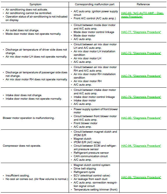
INSUFFICIENT COOLING
Description
Symptom
- Insufficient cooling
- No cool air comes out. (Air flow volume is normal.)
Diagnosis Procedure
Note:
Perform self-diagnoses with consult before performing symptom diagnosis. If any dtc is detected, perform the corresponding diagnosis.
1.Check magnet clutch operation
- Turn ignition switch on.
- Operate fan switch.
- PressA/Cswitch.
- Check that A/C indicator turns ON. Check visually and by sound that compressor operates.
- Press A/C switch again.
- Check that a/c indicator turns off. Check that compressor stops.
Is the inspection result normal? Yes >> go to 2.
No >> perform diagnosis of “compressor does not operate” in “symptom diagnosis”.
Refer to hac-102, "diagnosis procedure".
2.Check drive belt
Check tension of drive belt. Refer to em-16, "inspection".
Is the inspection result normal? Yes >> go to 3.
No >> adjust or replace drive belt depending on the inspection results.
3.Check refrigerant cycle
Connect recovery/recycling recharging equipment to the vehicle and perform pressure inspection with gauge.
Refer to ha-18, "symptom table".
Is the inspection result normal? Yes >> go to 4.
No >> repair or replace parts depending on the inspection results.
4.Check air leakage from each duct
Check duct and nozzle, etc. Of the front air conditioning system for leakage.
Is the inspection result normal? Yes >> go to 5.
No >> repair or replace parts depending on the inspection results.
5.Check ambient temperature display
Check that there is not much difference between actual ambient temperature and indicated temperature on information display in combination meter.
Is the inspection result normal? Yes >> go to 6.
No >> perform diagnosis for the a/c auto amp. Connection recognition signal circuit. Refer to hac-63, "diagnosis procedure".
6.Check setting of temperature setting trimmer (front)
- Check setting value of temperature setting trimmer (front). Refer to HAC-55, "Temperature Setting Trimmer".
- Check that temperature setting trimmer (front) is set to “+ direction”.
Note:
The control temperature can be set with the setting of the temperature setting trimmer (front).
- Set difference between set temperature and control temperature to “0”.
Is inspection result normal? YES >> Inspection End.
NO >> Replace A/C auto amp. Refer to HAC-105, "Removal and Installation".
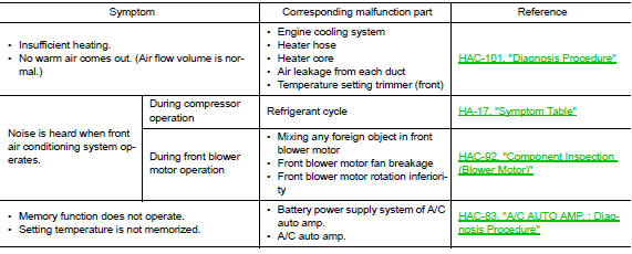
INSUFFICIENT HEATING
Description
Symptom
- Insufficient heating
- No warm air comes out. (Air flow volume is normal.)
Diagnosis Procedure
Note:
Perform self-diagnosis with consult before performing symptom diagnosis. If dtc is detected, perform the corresponding diagnosis.
1.Check cooling system
- Check engine coolant level and check leakage. Refer to co-11, "system inspection".
- Check reservoir tank cap. Refer to co-11, "system inspection".
- Check water flow sounds of the engine coolant. Refer to co-11, "system inspection".
Is the inspection result normal? Yes >> go to 2.
No >> refill engine coolant and repair or replace parts depending on the inspection results.
2.Check heater hose
Check installation of heater hose visually or by touching.
Is the inspection result normal? YES >> GO TO 3.
NO >> Repair or replace parts depending on the inspection results.
3.Check heater core
- Check temperature of inlet hose and outlet hose of front heater core.
- Check that inlet side of heater core is hot and the outlet side is slightly lower than/almost equal to the inlet side.
Caution:
Always perform the temperature inspection in a short period of time because the engine coolant temperature is very hot.
Is the inspection result normal? Yes >> go to 4.
No >> replace heater core. Refer to ha-44, "heater core : removal and installation".
4.Check air leakage from each duct
Check duct and nozzle, etc. Of front air conditioning system for air leakage.
Is the inspection result normal? Yes >> go to 5.
No >> repair or replace parts depending on the inspection results.
5.Check setting of temperature setting trimmer (front)
- Check setting value of temperature setting trimmer (front). Refer to hac-55, "temperature setting trimmer".
- Check that temperature setting trimmer (front) is set to “− direction”.
Note:
The control temperature can be set by the temperature setting trimmer (front).
- Set difference between the set temperature and control temperature to “0”.
Are the symptoms solved? Yes >> inspection end.
No >> replace a/c auto amp. Refer to hac-105, "removal and installation".
COMPRESSOR DOES NOT OPERATE
Description
Symptom: compressor does not operate.
Diagnosis Procedure
Note:
- Perform self-diagnoses with CONSULT before performing symptom diagnosis. If DTC is detected, perform the corresponding diagnosis.
- Check that refrigerant system is properly charged. If refrigerant amount is below the proper amount, perform inspection of refrigerant leakage.
1.Check magnet clutch operation
Check magnet clutch. Refer to HAC-94, "Component Function Check".
Does it operate normally? YES >> GO TO 2.
NO >> Repair or replace malfunctioning parts.
2.Check refrigerant pressure sensor
Check refrigerant pressure sensor. Refer to EC-465, "Component Function Check".
Is the inspection result normal? YES >> GO TO 3.
NO >> Repair or replace malfunctioning parts.
3.Check A/C Auto AMP. Output signal
 With CONSULT
Check “COMP REQ SIG” and “FAN REQ SIG” in “DATA MONITOR” mode of “HVAC” using CONSULT.
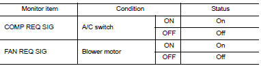
Is the inspection result normal? YES >> GO TO 4.
NO >> Replace A/C auto amp. Refer to HAC-105, "Removal and Installation".
4.Check ecm input signal
 With CONSULT
Check “AIR COND SIG” and “HEATER FAN SW” in “DATA MONITOR” mode of “ECM” using CONSULT.
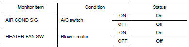
Is the inspection result normal? YES >> GO TO 5.
NO >> Check CAN communication system. Refer to LAN-16, "Trouble Diagnosis Flow Chart".
5.Check IPDM E/R Input signal
 With CONSULT
- Start engine.
- Check “AC COMP REQ” in “DATA MONITOR” mode of “IPDM E/R” using CONSULT.
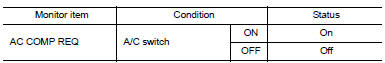
Is the inspection result normal? YES >> Inspection End.
NO >> Check CAN communication system. Refer to LAN-16, "Trouble Diagnosis Flow Chart".
 Power supply and ground circuit
A/C AUTO AMP
A/C AUTO AMP. : Diagnosis Procedure
Regarding Wiring Diagram information, refer to HAC-41, "Wiring Diagram".
1.CHECK FUSE
Check fuses [No. 5, 8 and 21, located in the fuse b ...
 Removal and installation
A/C SWITCH ASSEMBLY
Removal and Installation
REMOVAL
Remove the CVT shift selector finisher (CVT: RE0F11A). Refer to TM-253,
"Removal and Installation".
Remove the MT shift select ...
Other materials:
Precaution for supplemental restraint system (srs) "air bag" and "seat belt
pre-tensioner"
The Supplemental Restraint System such as “AIR BAG” and “SEAT BELT PRE-TENSIONER”,
used along
with a front seat belt, helps to reduce the risk or severity of injury to the
driver and front passenger for certain
types of collision. Information necessary to service the system ...
Removal and installation
A/C SWITCH ASSEMBLY
Removal and Installation
REMOVAL
Remove the CVT shift selector finisher (CVT: RE0F11A). Refer to TM-253,
"Removal and Installation".
Remove the MT shift selector finisher (6MT: RS6F94R). Refer to TM-22,
"Removal and Installation".
Remove the A/ ...
The fuel gauge indicator does not operate
Description
Fuel gauge will not indicate from a certain position.
Diagnosis procedure
1.CHECK FUEL LEVEL SENSOR SIGNAL CIRCUIT
Check the fuel level sensor signal circuit. Refer to MWI-58, "Diagnosis
Procedure".
Is the inspection result normal?
YES >> GO TO 2.
NO >> ...
