Nissan Sentra Service Manual: Steering gear and linkage
Inspection
INSPECTION AFTER DISASSEMBLY
BOOT
-
Check boot for cracks. Replace if any damage is found.
STEERING GEAR ASSEMBLY HOUSING
-
Check steering gear assembly housing for damage and scratches. Replace if there are any abnormal conditions.
OUTER SOCKET AND INNER SOCKET
Ball joint swinging torque
-
Hook a spring balance to the ball stud and inner socket measuring point (*) and pull the spring balance. Make sure that the spring balance reads the specified value when ball stud and inner socket start to move. Replace outer socket and inner socket if they are outside the specification.
Tool number : — (J-44372)
Swinging torque : Refer to ST-19, "Power Steering Gear".
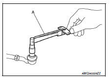
Ball joint rotating torque
-
Make sure that the reading is within the following specified range using Tool. Replace outer socket if the reading is outside the specification.
Tool number (A) : ST3127S000 (J-25765-A)
Rotating torque : Refer to ST-19, "Power Steering Gear".
INSPECTION AFTER INSTALLATION
-
Check if steering wheel turns smoothly when it is turned several times fully to the end of the left and right.
-
Check the steering wheel play, neutral position steering wheel, steering wheel turning force, and front wheel turning angle.
-
Steering wheel play: Refer to ST-5, "Inspection".
-
Neutral position steering wheel, steering wheel turning force, and front wheel turning angle: Refer to ST-5, "Inspection".
 Steering column
Inspection
STEERING COLUMN ASSEMBLY
Check each part of steering column assembly for damage or
other malfunctions. Replace entire steering column
assembly if any parts are damaged.
Me ...
 Symptom diagnosis
Noise, vibration and harshness (NVH) troubleshooting
NVH Troubleshooting Chart
Use the chart below to find the cause of the symptom. If
necessary, repair or replace these parts.
×: Appl ...
Other materials:
P0500 VSS
EXCEPT FOR M/T MODELS
EXCEPT FOR M/T MODELS : Description
ECM receives vehicle speed signals from two different paths via CAN
communication line: One is from the
ABS actuator and electric unit (control unit) via the combination unit and the
other is from TCM.
EXCEPT FOR M/T MODELS : DTC Logi ...
Unit removal and installation
TRANSAXLE ASSEMBLY
Exploded View
Transaxle assembly
Refer to INSTALLATION
Removal and Installation
WARNING:
Do not remove the radiator cap when the engine is hot. Serious burns
could occur from high pressure
coolant escaping from the radiator. Wrap a thick cloth around the cap. ...
Diagnosis and repair workflow
Work flow
Overall sequence
Detailed flow
1. Obtain information about symptom
Interview the customer to obtain as much information as possible about the
conditions and environment under
which the malfunction occurred.
>> GO TO 2.
2. Confirm concern
Check the malfunction on the veh ...
