Nissan Sentra Service Manual: Road wheel tire assembly
Exploded View
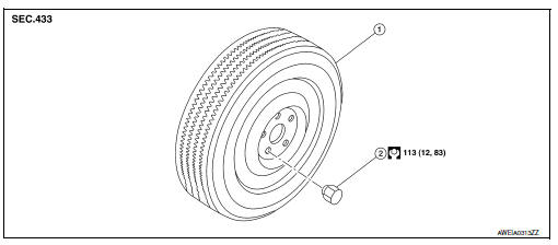
Removal and Installation
REMOVAL
- Remove wheel nuts.
- Remove wheel and tire.
INSTALLATION
Installation is in the reverse order of removal.
Adjustment
BALANCING WHEELS (ADHESIVE WEIGHT TYPE)
Preparation Before Adjustment
Remove inner and outer balance weights from the road wheel. Using releasing agent, remove double-faced adhesive tape from the road wheel.
CAUTION:
- Be careful not scratch the road wheel during removal.
- After removing double-faced adhesive tape, wipe clean all traces of releasing agent from the road wheel.
Wheel Balance Adjustment
- If a balancer machine has an adhesive weight mode setting, select the
adhesive weight mode setting and
skip Step 2. below. If a balancer machine only has the clip-on (rim flange)
weight mode setting, follow Step 2.
to calculate the correct size adhesive weight.
- Set road wheel on balancer machine using the center hole as a guide. Start the balancer machine.
- For balancer machines that only have a clip-on (rim flange) weight mode setting, follow this step to calculate the correct size adhesive weight to use. When inner and outer imbalance values are shown on the balancer machine indicator, multiply outer imbalance value by 5/3 (1.67) to determine balance weight that should be used. Select the outer balance weight with a value closest to the calculated value above and install in to the designated outer position of, or at the designated angle in relation to the road wheel.
- Indicated imbalance value × 5/3 (1.67) = balance weight to be installed
Calculation example:
23 g (0.81 oz) × 5/3 (1.67) = 38.33 g (1.35 oz) ⇒ 40 g (1.41 oz) balance weight (closer to calculated balance weight value)
NOTE:
Note that balance weight value must be closer to the calculated balance weight value.
Example:
37.4 ⇒ 35 g (1.23 oz) 37.5 ⇒ 40 g (1.41 oz)
- Install balance weight in the position shown.
CAUTION:
- Do not install the inner balance weight before installing the outer balance weight.
- Before installing the balance weight, be sure to clean the mating surface of the road wheel.
- When installing balance weight (1) to road wheel, set it into the grooved area (A) on the inner wall of the road wheel as shown so that the balance weight center (B) is aligned with the balancer machine indication position (angle) (C).
CAUTION:
- Always use genuine NISSAN adhesive balance weights.
- Balance weights are non-reusable; always replace with new ones.
- Do not install more than three sheets of balance weight.
- If calculated balance weight value exceeds 50 g (1.76 oz), install two balance weight sheets in line with each other as shown.
CAUTION:
Do not install one balance weight sheet on top of another.
- Start balancer machine again.
- Install balance weight on inner side of road wheel in the balancer machine indication position (angle).
CAUTION:
Do not install more than two balance weights.
- Start balancer machine. Make sure that inner and outer residual imbalance values are 5 g (0.18 oz) each or below.
- If either residual imbalance value exceeds 5 g (0.18 oz), repeat installation procedures.
Allowable imbalance Refer to WT-54, "Road Wheel".
TIRE ROTATION
- Follow the maintenance schedule for tire rotation service intervals.
Refer to MA-5, "Explanation of General Maintenance".
- When installing the wheel, tighten wheel nuts to the specified torque.
CAUTION:
- Do not include the T-type spare tire when rotating the tires.
- When installing wheels, tighten them diagonally by dividing the work two to three times in order to prevent the wheels from developing any distortion.
- Be careful not to tighten wheel nut at torque exceeding the criteria for preventing strain of disc rotor.
- Use NISSAN genuine wheel nuts for aluminum wheels.
Wheel nut tightening torque Refer to WT-54, "Road Wheel".

 Transmitter
Exploded View
Transmitter (tire pressure sensor)
O-ring
Valve stem nut
Valve core
Valve cap
Valve stem assembly
Parts that are replaced as a set
when the tire is replaced.
Remo ...
Other materials:
Rearview mirror (if so equipped)
The night position 1 reduces glare from the
headlights of vehicles behind you at night.
Use the day position 2 when driving in daylight
hours.
WARNINGUse the night position only when
necessary,
because it reduces rear view clarity.
...
Basic inspection
Diagnosis and repair workflow
Work flow
OVERALL SEQUENCE
DETAILED FLOW
1.INTERVIEW FOR MALFUNCTION
Find out what the customer's concerns are.
>> GO TO 2.
2.SYMPTOM CHECK
Verify the symptom from the customer's information.
>> GO TO 3.
3.BASIC INSPECTION
Check the operat ...
P0037, P0038 HO2S2 Heater
DTC Logic
DTC DETECTION LOGIC
DTC No.
CONSULT screen terms
(Trouble diagnosis content)
DTC detecting condition
Possible cause
P0037
HO2 HTR (B1)
(HO2S heater control circuit
low bank 1 sensor 2)
The current amperage in the heated oxygen sensor
2 heater ci ...
