Nissan Sentra Service Manual: P0037, P0038 HO2S2 Heater
DTC Logic
DTC DETECTION LOGIC
| DTC No. | CONSULT screen terms (Trouble diagnosis content) | DTC detecting condition | Possible cause |
| P0037 | HO2 HTR (B1) (HO2S heater control circuit low bank 1 sensor 2) | The current amperage in the heated oxygen sensor
2 heater circuit is out of the normal range.
(An excessively low voltage signal is sent to ECM through the heated oxygen sensor 2 heater.) |
|
| P0038 | HO2 HTR (B1) (HO2S heater control circuit high bank 1 sensor 2) | The current amperage in the heated oxygen sensor
2 heater circuit is out of the normal range.
(An excessively high voltage signal is sent to ECM through the heated oxygen sensor 2 heater.) |
|
DTC CONFIRMATION PROCEDURE
1.PRECONDITIONING
If DTC Confirmation Procedure has been previously conducted, always perform the following procedure before conducting the next test.
- Turn ignition switch OFF and wait at least 10 seconds.
- Turn ignition switch ON.
- Turn ignition switch OFF and wait at least 10 seconds.
TESTING CONDITION:
Before performing the following procedure, confirm that battery voltage is more than 11 V at idle.
>> GO TO 2.
2.PERFORM DTC CONFIRMATION PROCEDURE
 With CONSULT
- Turn ignition switch ON and select “DATA MONITOR” mode of “ENGINE” using CONSULT.
- Start engine and warm it up to normal operating temperature.
- Turn ignition switch OFF and wait at least 10 seconds.
- Start engine and keep the engine speed between 3,500 and 4,000 rpm for at least 1 minute under no load
- Let engine idle for 1 minute.
- Check 1st trip DTC.
 With GST
Follow the procedure “With CONSULT” above.
Is 1st trip DTC detected?
YES >> Proceed to EC-178, "Diagnosis Procedure".
NO >> INSPECTION END
Diagnosis Procedure
1.CHECK HO2S2 POWER SUPPLY CIRCUIT
- Turn ignition switch OFF.
- Disconnect heated oxygen sensor 2 (HO2S2) harness connector.
- Turn ignition switch ON.
- Check the voltage between HO2S2 harness connector and ground.
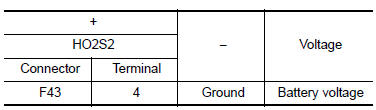
Is the inspection result normal? YES >> GO TO 2.
NO >> Repair or replace error-detected parts.
2.CHECK HO2S2 OUTPUT SIGNAL CIRCUIT
- Turn ignition switch OFF.
- Disconnect ECM harness connector.
- Check the continuity between HO2S2 harness connector and ECM harness connector.
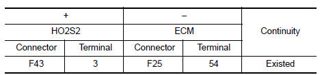
- Also check harness for short to ground and short to power.
Is the inspection result normal? YES >> GO TO 3.
NO >> Repair or replace error-detected parts.
3.CHECK HEATED OXYGEN SENSOR 2 HEATER
Check the heated oxygen sensor 2 heater. Refer to EC-179, "Component Inspection (HO2S Heater)".
Is the inspection result normal? YES >> Check intermittent incident. Refer to GI-39, "Intermittent Incident".
NO >> Replace heated oxygen sensor 2. Refer to EX-5, "Exploded View".
Component Inspection (HO2S Heater)
1.CHECK HEATED OXYGEN SENSOR 2 HEATER
- Turn ignition switch OFF.
- Disconnect heated oxygen sensor 2 (HO2S2) harness connector.
- Check resistance between HO2S2 terminals as per the following
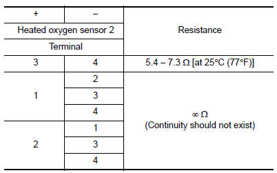
Is the inspection result normal? YES >> INSPECTION END
NO >> Replace heated oxygen sensor 2. Refer to EX-5, "Exploded View".
 P0031, P0032 A/F sensor 1 Heater
DTC Logic
DTC DETECTION LOGIC
DTC No.
CONSULT screen terms
(Trouble diagnosis content)
DTC detecting condition
Possible cause
P0031
A/F SEN 1 HTR (B1)
(HO2S heater ...
 P0075 IVT control solenoid valve
DTC Logic
DTC DETECTION LOGIC
DTC No.
CONSULT screen terms
(Trouble diagnosis content)
DTC detecting condition
Possible cause
P0075
INT/V TIM V/CIR-B1
(Intake valve ...
Other materials:
P0182, P0183 FTT Sensor
DTC Logic
DTC DETECTION LOGIC
DTC No.
CONSULT screen terms
(Trouble diagnosis content)
DTC detecting condition
Possible cause
P0182
FTT SEN/CIRCUIT
(Fuel temperature sensor
″A″ circuit low)
An excessively low voltage from the sensor is
sent to ...
How to Follow Test Groups in Trouble Diagnosis
Test group number and test group title
Test group number and test group title are shown in the upper portion of
each test group.
Work and diagnosis procedure
Start to diagnose a problem using procedures indicated in enclosed test
groups.
Questions and results
...
Component parts
Component Parts Location
BCM (view with instrument panel removed)
Remote keyless entry receiver (view
with instrument panel removed)
Transmitter
Combination meter
Component Description
BCM
The BCM reads the tire pressure signal received by the remote keyless entry
receiver ...
