Nissan Sentra Service Manual: Basic inspection
Diagnosis and repair workflow
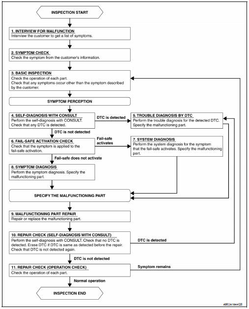
Work flow
OVERALL SEQUENCE
DETAILED FLOW
1.INTERVIEW FOR MALFUNCTION
Find out what the customer's concerns are.
>> GO TO 2.
2.SYMPTOM CHECK
Verify the symptom from the customer's information.
>> GO TO 3.
3.BASIC INSPECTION
Check the operation of each part. Check that any concerns occur other than those mentioned in the customer interview.
>> GO TO 4.
4.SELF-DIAGNOSIS WITH CONSULT
Perform the self-diagnosis with CONSULT. Check that any DTC is detected.
Is any DTC detected? YES >> GO TO 5.
NO >> GO TO 6.
5.TROUBLE DIAGNOSIS BY DTC
Perform the trouble diagnosis for the detected DTC. Specify the malfunctioning part.
>> GO TO 9.
6.FAIL-SAFE ACTIVATION CHECK
Determine if the customer's concern is related to fail-safe activation.
Does the fail-safe activate? YES >> GO TO 7.
NO >> GO TO 8.
7.SYSTEM DIAGNOSIS
Perform the system diagnosis for the system in which the fail-safe activates. Specify the malfunctioning part.
>> GO TO 9.
8.SYMPTOM DIAGNOSIS
Perform the symptom diagnosis, refer to INL-51, "Symptom Table". Specify the malfunctioning part.
>> GO TO 9.
9.MALFUNCTION PART REPAIR
Repair or replace the malfunctioning part.
>> GO TO 10.
10.REPAIR CHECK (SELF-DIAGNOSIS WITH CONSULT)
Perform the self-diagnosis with CONSULT. Verify that no DTCs are detected. Erase all DTCs detected prior to the repair. Verify that DTC is not detected again.
Is any DTC detected? YES >> GO TO 5.
NO >> GO TO 11.
11.REPAIR CHECK (OPERATION CHECK)
Check the operation of each part.
Does it operate normally? YES >> Inspection End.
NO >> GO TO 3.
 Wiring diagram
Interior room lamp control system
Wiring diagram
Illumination
Wiring diagram
...

Other materials:
Fuses
Two types of fuses are used. Type A is used in
the fuse boxes in the engine compartment. Type
B is used in the passenger compartment fuse
box.
Type A fuses are provided as spare fuses. They
are stored in the passenger compartment fuse
box.
Type A fuses can be installed in the engine com ...
Precautions for refrigerant system service
WORKING WITH HFC-134a (R-134a)
CAUTION:
CFC-12 (R-12) refrigerant and HFC-134a (R-134a) refrigerant are
not compatible. Compressor malfunction
is likely to occur if the refrigerants are mixed, refer to “CONTAMINATED
REFRIGERANT”
below. To determine the purity of HFC-134a (R- ...
System
CVT CONTROL SYSTEM
CVT CONTROL SYSTEM : System Diagram
CVT CONTROL SYSTEM : System Description
DESCRIPTION
CVT detects the vehicle driving status from switches, sensors and
signals, and controls the vehicle so that
the optimum shift position and shift timing may always be achieved ...
