Nissan Sentra Service Manual: Repairing material
Foam Repair
During factory assembly, foam insulators are installed in certain body panels and locations around the vehicle.
Use the following procedure(s) to replace any factory-installed foam insulators.
URETHANE FOAM APPLICATIONS
Use commercially available Urethane foam for sealant (foam material) repair of material used on vehicle.
<Urethane foam for foaming agent> 3Mв„ў Automixв„ў Flexible Foam 08463 or equivalent
Read instructions on product for fill procedures.
FILL PROCEDURES
Example of foaming agent filling operation procedure:
- Fill procedures after installation of service part.
- Eliminate foam material remaining on vehicle side.
- Clean area after eliminating form insulator and foam material.
- Install service part.
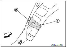
- Insert nozzle into hole (A) near fill area and fill foam material (1) or fill enough to close gap with the service part.
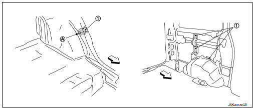
- Urethane foam
- Nozzle insert hole
 Front
Front
- Fill procedures before installation of service part:
- Eliminate foam material remaining on vehicle side.
- Clean area after eliminating foam insulator and foam material.
- Fill with enough foam material on the wheelhouse outer side to close the gap with the service part while avoiding the flange area.
- Urethane foam
- Fill while avoiding flange area
 : Front
- Install service part.
NOTE:
Refer to the label on the urethane foam container for information on working times.
- Body side outer
- Body side insulation (foam) front pillar
- Body side insulation (foam) roof side rail
- Roof panel assembly
- Body side insulation (foam) rear pillar
- Body side insulation (foam) rear pillar lower
- Body side insulation strip, front pillar lower reinforcement
 Front
Front
 Preparation
...
 Body component parts
Moonroof panel assembly
Roof panel assembly
Front roof rail
Roof rail
Rear roof rail
Moonroof frame assembly
Hood assembly
Front fender (RH, LH)
Outer front door panel (RH, LH)
...
Other materials:
Loading tips
The GVW must not exceed GVWR
or GAWR as specified on the
F.M.V.S.S./C.M.V.S.S. certification
label.
Do not load the front and rear axle to
the GAWR. Doing so will exceed the
GVWR.
WARNING
Properly secure all cargo with
ropes or straps to help prevent it
from slid ...
Basic inspection
Diagnosis and repair workflow
Work Flow
Overall sequence
Detailed flow
1.Get information for symptom
Get detailed information from the customer about the symptom (the condition
and the environment when the
incident/malfunction occurred).
>> GO TO 2.
2.Confirm the symptom
Try t ...
Slip indicator lamp
Component Function Check
1.CHECK SLIP INDICATOR LAMP FUNCTION
Check that slip indicator lamp in combination meter turns ON for
approximately 2 seconds after ignition switch
is turned ON.
Is the inspection result normal?
YES >> Inspection End.
NO >> Proceed to diagnosis proce ...
