Nissan Sentra Service Manual: Removal and installation
OIL COOLER
Exploded View
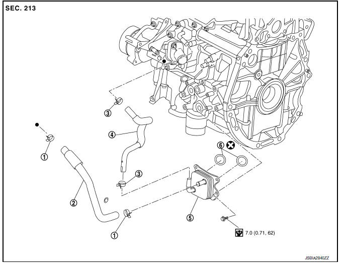
M/T models
- Clamp
- Water hose
- Clamp
- Water hose
- Oil cooler
- O-rings
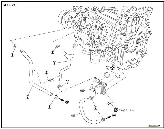
CVT models
- Clamp
- Water hose
- Clamp
- Water hose
- Water hose clip
- Oil cooler
- Clamp
- Water hose
- O-rings
- To CVT oil warmer
Removal and Installation
REMOVAL
- Remove engine under cover. Refer to EXT-16, "Exploded View".
- Drain engine coolant. Refer to CO-12, "Changing Engine Coolant".
CAUTION:
Perform when engine is cold.
- Remove water hoses.
- Remove bolts, oil cooler and O-rings.
CAUTION:
- Be careful not to get burned when engine and engine oil may be hot.
- When removing, prepare a shop cloth to absorb any engine oil leaks or spills.
- Completely wipe off any engine oil that adheres to engine and vehicle.
INSTALLATION
Installation is in the reverse order of removal.
CAUTION:
Do not reuse O-rings.
NOTE:
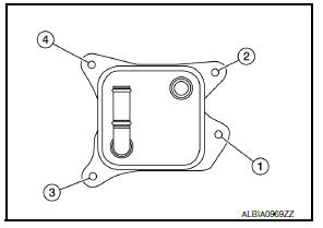
Tighten the oil cooler bolts in order as shown to specification.
Inspection
INSPECTION AFTER REMOVAL
Oil Cooler
Check oil cooler for cracks. Check oil cooler for clogging by blowing through engine coolant inlet. If necessary, replace oil cooler assembly.
INSPECTION AFTER INSTALLATION
- Check the engine oil level and the engine coolant level and add engine oil and engine coolant. Refer to LU-7, "Inspection" and CO-11, "System Inspection".
- Start the engine, and check that there are no leaks of engine oil or engine coolant.
- Stop the engine and wait for 10 minutes.
- Check the engine oil level and the engine coolant level again. Refer to LU-7, "Inspection" and CO-11, "System Inspection".
 Oil filter
Removal and Installation
REMOVAL
Remove engine under cover. Refer to EXT-16, "Exploded View".
Drain engine oil. Refer to LU-8, "Draining".
Remove the oil filter using Too ...
 Unit disassembly and assembly
OIL PUMP
O-ring
Oil pan (upper)
Oil level gauge guide
O-ring
Oil level gauge
Oil pump chain tensioner
Oil pump drive chain
Crankshaft sprocket
Oil pump sprocket
Oil pump
Dr ...
Other materials:
System description
Component parts
Component parts location
Front tweeter lh (if equipped)
Steering switches
Audio unit
Front tweeter rh (if equipped)
Microphone (if equipped)
Front door speaker lh
Front door speaker RH
Rear speaker rh
Rear speaker lh
Antenna amp.
Window antenna
Bluetoot ...
Steering wheel
Exploded View
Driver air bag module
Steering wheel
Steering column assembly
Removal and Installation
REMOVAL
NOTE:
When reconnecting spiral cable, fix cable with a tape so that
fixing case and rotating part keep aligned. This
will omit neutral position alignment procedu ...
Speedometer and odometer
Speedometer
The speedometer indicates the vehicle speed.
Odometer/Twin trip odometer
The odometer 2 and the twin trip odometer 1
are displayed when the ignition switch is placed
in the ON position.
The odometer records the total distance the vehicle
has been driven.
The twin trip o ...
