Nissan Sentra Service Manual: Unit disassembly and assembly
OIL PUMP
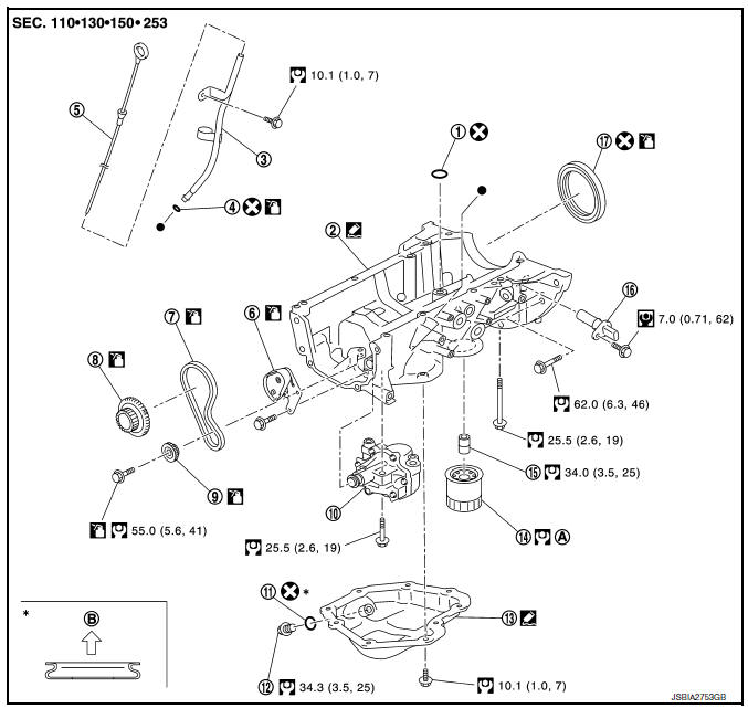
- O-ring
- Oil pan (upper)
- Oil level gauge guide
- O-ring
- Oil level gauge
- Oil pump chain tensioner
- Oil pump drive chain
- Crankshaft sprocket
- Oil pump sprocket
- Oil pump
- Drain plug washer
- Drain plug
- Oil pan (lower)
- Oil filter
- Connector bolt
- Crankshaft position sensor
- Rear oil seal
- Refer to LU-10, "Removal and Installation"
- Oil pan side
Removal and Installation
REMOVAL
- Remove engine under cover. Refer to EXT-16, "Exploded View".
- Remove air cleaner and air duct. Refer toEM-25, "Removal and Installation".
- Remove fender protector. Refer to EXT-28, "FENDER PROTECTOR : Removal and Installation - Front Fender Protector".
- Remove timing chain. Refer to EM-49, "Removal and Installation".
- Remove oil pump.
- Loosen bolts in reverse order as shown.
(1) : Oil pump
(2) : Oil pan (upper)
INSTALLATION
CAUTION:
Do not reuse O-rings or washers.
Installation is in the reverse order of removal.
Oil Pump
- Tighten bolts in numerical order as shown.
(1) : Oil pump
(2) : Oil pan (upper)
Inspection
INSPECTION AFTER INSTALLATION
- Check the engine oil level. Refer to LU-7, "Inspection".
- Start the engine, and check that there are no leaks of engine oil.
- Stop the engine and wait for 10 minutes.
- Check the engine oil level, and adjust the level. Refer to LU-7, "Inspection".
 Removal and installation
OIL COOLER
Exploded View
M/T models
Clamp
Water hose
Clamp
Water hose
Oil cooler
O-rings
CVT models
Clamp
Water hose
Clamp
Water hose
Water hose clip
Oil coole ...
 Service data and specifications
(SDS)
Service data and specifications
(SDS)
Oil pressure
*: Engine oil temperature at 80В°C (176В°F)
Oil Capacity
...
Other materials:
Child safety
WARNINGDo not allow children to play with the
seat
belts. Most seating positions are
equipped with Automatic Locking Retractor
(ALR) mode seat belts. If the seat belt
becomes wrapped around a child’s neck
with the ALR mode activated, the child can
be seriously injured ...
System
Interior room lamp control system
INTERIOR ROOM LAMP CONTROL SYSTEM : System Diagram
WITH INTELLIGENT KEY
WITHOUT INTELLIGENT KEY
INTERIOR ROOM LAMP CONTROL SYSTEM : System Description
OUTLINE
Interior room lamp* is controlled by the interior room lamp timer
control function of t ...
P1652 Starter motor system comm
Description
ECM controls ON/OFF state of the starter relay, according to the engine and
vehicle condition. ECM transmits
a control signal to IPDM E/R via BCM by CAN communication.
Under normal conditions, ECM controls and maintains the starter relay in OFF
state during following condition:
...
