Nissan Sentra Service Manual: Power supply and ground circuit
Av control unit
Av control unit : diagnosis procedure
Regarding wiring diagram information, refer to av-331, "wiring diagram".
1.Check fuse
Check that the following fuses are not blown.
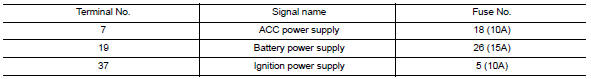
Are the fuses blown? Yes >> replace the blown fuse after repairing the affected circuit.
No >> go to 2.
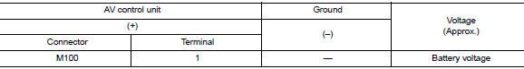
2.Check power supply circuit
- Turn ignition switch OFF.
- Disconnect av control unit connectors m100 and m101.
- Check voltage between AV control unit connectors M100 and M101 and ground.
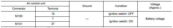
Is the inspection result normal? YES >> GO TO 3.
NO >> Repair or replace harness or connectors.
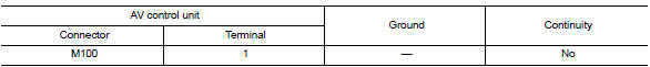
3.Check ground circuit
- Turn ignition switch off.
- Check continuity between av control unit connector m100 and ground.

Is the inspection result normal? Yes >> inspection end.
No >> repair or replace harness or connectors.
Bose speaker amp
Bose speaker amp : diagnosis procedure
Regarding Wiring Diagram information, refer to AV-331, "Wiring Diagram".
1.Check fuse
Check that the following fuses are not blown.
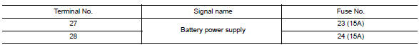
Are the fuses blown? YES >> Replace the blown fuse after repairing the affected circuit.
NO >> GO TO 2.
2.Check power supply circuit
- Turn ignition switch off.
- Disconnect bose speaker amp. Connector b44.
- Check voltage between bose speaker amp. Connector b44 and ground.
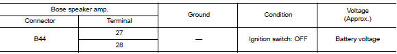
Is the inspection result normal? Yes >> go to 3.
No >> repair or replace harness or connectors.
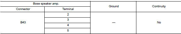
3.Check ground circuit
- Turn ignition switch off.
- Disconnect bose speaker amp. Connector b44.
- Check continuity between Bose speaker amp. connector B44 and ground.
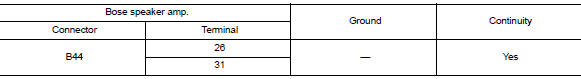
Is the inspection result normal? Yes >> inspection end.
No >> repair or replace harness or connectors.
Front door speaker
Diagnosis procedure
Regarding Wiring Diagram information, refer to AV-331, "Wiring Diagram".
1.Connector check
Check the av control unit, bose speaker amp. And speaker connectors for the following:
- Proper connection
- Damage
- Disconnected or loose terminals
Is the inspection result normal? Yes >> go to 2
No >> repair the terminals or connectors.
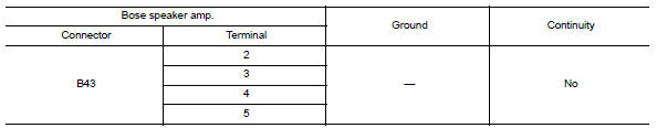
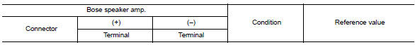
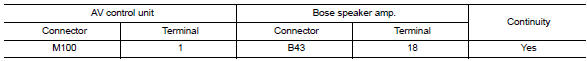
2.Check front door speaker signal circuit continuity (bose speaker amp.)
- Disconnect bose speaker amp. Connector b43 and suspect front door speaker connector.
- Check continuity between bose speaker amp. Connector b43 and suspect front door speaker connector.
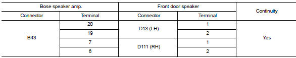
- Check continuity between bose speaker amp. Connector b43 and ground.
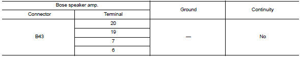
Is the inspection result normal? Yes >> go to 3
No >> repair or replace harness or connectors.
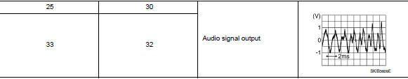
3.Check front door speaker signal (bose speaker amp.)
- Connect bose speaker amp. Connector b43 and suspect front door speaker connector.
- Turn ignition switch to ACC.
- Push AV control unit POWER switch.
- Check signal between the terminals of bose speaker amp. Connector b43.
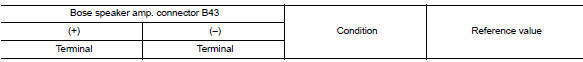
Is the inspection result normal? YES >> Replace front door speaker. Refer to AV-408, "Removal and Installation".
NO >> GO TO 4
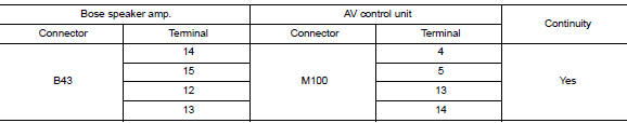
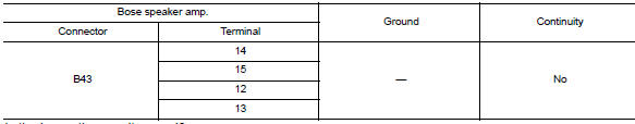
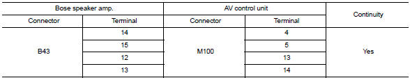
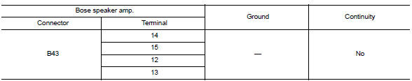
4.Check front door speaker signal circuit continuity (av control unit)
- Turn ignition switch to OFF.
- Disconnect bose speaker amp. Connector b43 and av control unit connector m100.
- Check continuity between bose speaker amp. Connector b43 and av control unit connector m100.
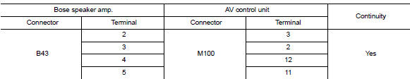
- Check continuity between bose speaker amp. Connector b43 and ground.
Is the inspection result normal? Yes >> go to 5
No >> repair or replace harness or connectors.
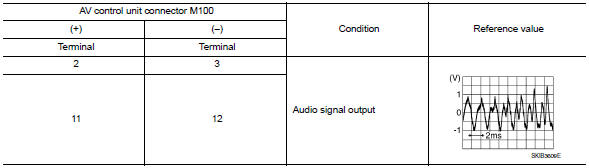
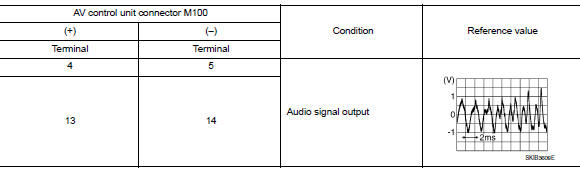
5.Check front door speaker signal (av control unit)
- Connect bose speaker amp. Connector b43 and av control unit connector m100.
- Turn ignition switch to ACC.
- Push av control unit power switch.
- Check signal between av control unit connector m100 and ground.
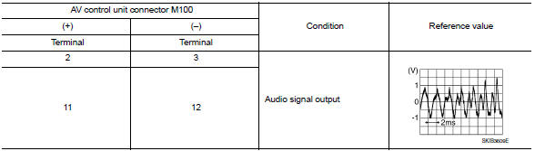
Is the inspection result normal?
Yes >> replace bose speaker amp. Refer to av-417, "removal and installation".
No >> replace av control unit. Refer to av-406, "removal and installation".
Front tweeter
Diagnosis procedure
Regarding wiring diagram information, refer to av-331, "wiring diagram".
1.Connector check
Check the av control unit, bose speaker amp. And speaker connectors for the following:
- Proper connection
- Damage
- Disconnected or loose terminals
Is the inspection result normal? YES >> GO TO 2
No >> repair the terminals or connectors.
2.Check front speaker signal circuit continuity (bose speaker amp.)
- Disconnect bose speaker amp. Connector b44 and suspect front speaker connector.
- Check continuity between bose speaker amp. Connector b44 and suspect front speaker connector.
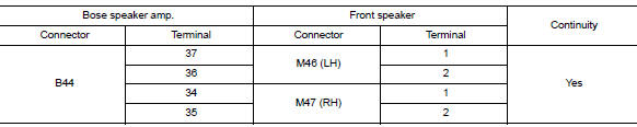
- Check continuity between bose speaker amp. Connector b44 and ground.
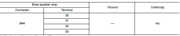
Is the inspection result normal? Yes >> go to 3
No >> repair or replace harness or connectors.
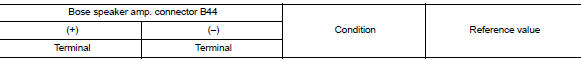
3.Check front speaker signal (bose speaker amp.)
- Connect bose speaker amp. Connector b44 and suspect front speaker connector.
- Turn ignition switch to ACC.
- Push av control unit power switch.
- Check signal between the terminals of bose speaker amp. Connector b44.
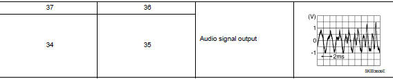
Is the inspection result normal? Yes >> replace front tweeter. Refer to av-407, "removal and installation".
No >> go to 4
4.Check front speaker signal circuit continuity (av control unit)
- Turn ignition switch to OFF.
- Disconnect Bose speaker amp. connector B43 and AV control unit connector M100.
- Check continuity between Bose speaker amp. connector B43 and AV control unit connector M100.
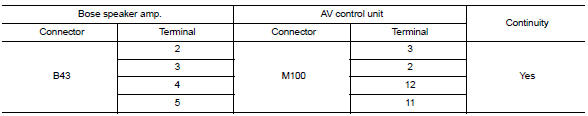
- Check continuity between bose speaker amp. Connector b43 and ground.
Is the inspection result normal? Yes >> go to 5
NO >> Repair or replace harness or connectors.
5.Check front speaker signal (av control unit)
- Connect bose speaker amp. Connector b43 and av control unit connector m100.
- Turn ignition switch to ACC.
- Push av control unit power switch.
- Check signal between av control unit connector m100 and ground.
Is the inspection result normal?
YES >> Replace Bose speaker amp. Refer to AV-417, "Removal and Installation".
NO >> Replace AV control unit. Refer to AV-406, "Removal and Installation".
Rear door speaker
Diagnosis procedure
Regarding wiring diagram information, refer to av-331, "wiring diagram".
1.Connector check
Check the AV control unit, Bose speaker amp. and speaker connectors for the following:
- Proper connection
- Damage
- Disconnected or loose terminals
Is the inspection result normal? Yes >> go to 2
No >> repair the terminals or connectors.
2.Check rear door speaker signal circuit continuity (bose speaker amp.)
- Disconnect Bose speaker amp. connectors and suspect rear door speaker connector.
- Check continuity between bose speaker amp. Connectors and suspect rear door speaker connector.
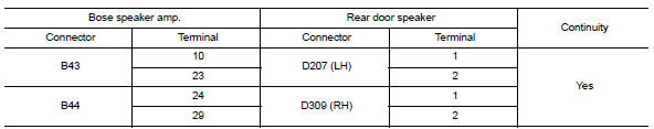
- Check continuity between Bose speaker amp. connectors and ground.
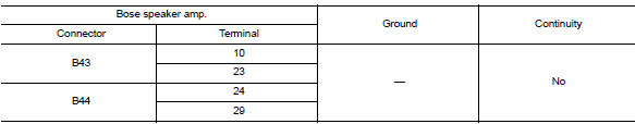
Is the inspection result normal? Yes >> go to 3
NO >> Repair or replace harness or connectors.
3.Check rear door speaker signal (bose speaker amp.)
- Connect Bose speaker amp. connectors and suspect rear door speaker connector.
- Turn ignition switch to acc.
- Push av control unit power switch.
- Check signal between terminals of Bose speaker amp. connectors.
Is the inspection result normal? Yes >> replace rear door speaker. Refer to av-409, "removal and installation".
No >> go to 4
4.Check rear door speaker signal circuit continuity (av control unit)
- Turn ignition switch to OFF.
- Disconnect bose speaker amp. Connector b43 and av control unit connector m100.
- Check continuity between bose speaker amp. Connector b43 and av control unit connector m100.
- Check continuity between bose speaker amp. Connector b43 and ground.
Is the inspection result normal? Yes >> go to 5
No >> repair or replace harness or connectors.
5.Check rear door speaker signal (av control unit)
- Connect bose speaker amp. Connector b43 and av control unit connector m100.
- Turn ignition switch to acc.
- Push av control unit power switch.
- Check signal between AV control unit connector M100 and ground.
Is the inspection result normal?
YES >> Replace Bose speaker amp. Refer to AV-417, "Removal and Installation".
NO >> Replace AV control unit. Refer to AV-406, "Removal and Installation".
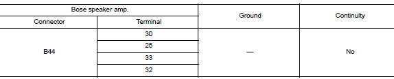
Rear woofer
Diagnosis procedure
Regarding wiring diagram information, refer to av-331, "wiring diagram".
1.Connector check
Check the av control unit, bose speaker amp. And speaker connectors for the following:
- Proper connection
- Damage
- Disconnected or loose terminals
Is the inspection result normal? Yes >> go to 2
No >> repair the terminals or connectors.
2.Check rear woofer signal circuit continuity (bose speaker amp.)
- Disconnect Bose speaker amp. connector B44 and suspect rear woofer connector.
- Check continuity between bose speaker amp. Connector b44 and suspect rear woofer connector.
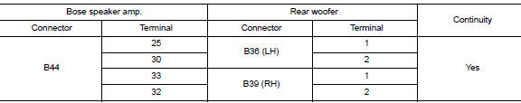
- Check continuity between bose speaker amp. Connector b44 and ground.
Is the inspection result normal? Yes >> go to 3
No >> repair or replace harness or connectors.
3.Check rear woofer signal (bose speaker amp.)
- Connect bose speaker amp. Connector b44 and suspect rear woofer connector.
- Turn ignition switch to acc.
- Push av control unit power switch.
- Check signal between terminals of Bose speaker amp. connector B44.
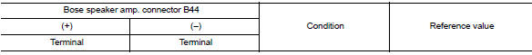
Is the inspection result normal? Yes >> replace rear woofer. Refer to av-410, "removal and installation".
No >> go to 4
4.Check rear woofer signal circuit continuity (av control unit)
- Turn ignition switch to OFF.
- Disconnect Bose speaker amp. connector B43 and AV control unit connector M100.
- Check continuity between Bose speaker amp. connector B43 and AV control unit connector M100.
- Check continuity between Bose speaker amp. connector B43 and ground.
Is the inspection result normal? YES >> GO TO 5
NO >> Repair or replace harness or connectors.
5.Check rear woofer signal (av control unit)
- Connect Bose speaker amp. connector B43 and AV control unit connector M100.
- Turn ignition switch to ACC.
- Push AV control unit POWER switch.
- Check signal between AV control unit connector M100 and ground.
Is the inspection result normal?
YES >> Replace Bose speaker amp. Refer to AV-417, "Removal and Installation".
NO >> Replace AV control unit. Refer to AV-406, "Removal and Installation".
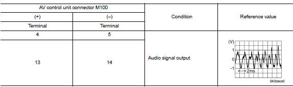
Amp on signal circuit
Diagnosis Procedure
Regarding wiring diagram information, refer to av-331, "wiring diagram".
1.Check continuity between av control unit and bose speaker amp.
- Turn ignition switch off.
- Disconnect av control unit connector m100 and bose speaker amp. Connector b43.
- Check continuity between AV control unit connector M100 and Bose speaker amp. connector B43.
- Check continuity between av control unit connector m100 and ground.
Is the inspection result normal? YES >> GO TO 2.
NO >> Repair or replace harness or connectors.
2.Check av control unit voltage
- Connect av control unit connector m100.
- Turn ignition switch ON.
- Check voltage between av control unit connector m100 and ground.
Is the inspection result normal? Yes >> replace bose speaker amp. Refer to av-417, "removal and installation".
No >> replace av control unit. Refer to av-406, "removal and installation".
Rear view camera image signal circuit
Diagnosis procedure
Regarding wiring diagram information, refer to av-331, "wiring diagram".
1.Check reverse input signal
- Turn ignition switch on.
- Shift the selector lever to r (reverse).
- Check voltage between AV control unit connector M101 and ground.
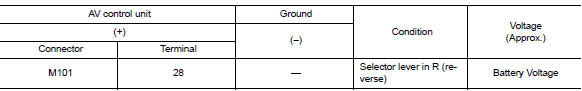
Is inspection result normal? Yes >> go to 2.
No >> repair or replace harness or connectors.
2.Check camera power supply circuit continuity
- Turn ignition switch OFF.
- Disconnect AV control unit connector M101 and rear view camera connector.
- Check continuity between av control unit connector m101 and rear view camera connector b30.
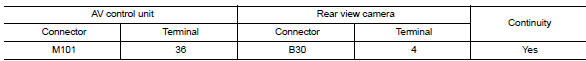
- Check continuity between av control unit connector m101 and ground.
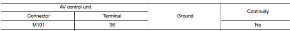
Is inspection result normal? Yes >> go to 3.
No >> repair or replace harness or connectors.
3.Check camera power supply voltage
- Connect AV control unit connector M101 and rear view camera connector.
- Turn ignition switch on.
- Shift the selector lever to R (reverse).
- Check voltage between av control unit connector m101 and ground.
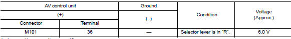
Is inspection result normal? Yes >> go to 4.
No >> replace av control unit. Refer to av-406, "removal and installation".
4.Check camera image signal circuit continuity
- Turn ignition switch OFF.
- Disconnect av control unit connector m101 and rear view camera connector.
- Check continuity between AV control unit connector M101 and rear view camera connector B30.
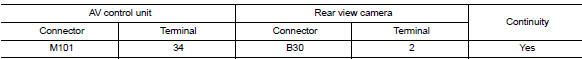
- Check continuity between av control unit connector m101 terminal 34 and ground.
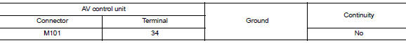
Is inspection result normal? YES >> GO TO 5.
NO >> Repair or replace harness or connectors.
5.Check camera ground circuit continuity
Check continuity between av control unit connector m101 and rear view camera connector b30.
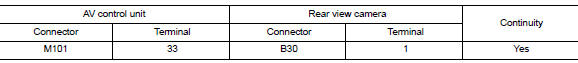
Is inspection result normal? Yes >> go to 6.
No >> repair or replace harness or connectors.
6.Check camera image signal
- Connect av control unit connector m101 and rear view camera connector.
- Turn ignition switch on.
- Shift the selector lever to r (reverse).
- Check signal between av control unit connector m101 and ground.
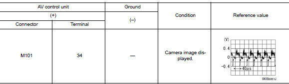
Is inspection result normal? Yes >> replace av control unit. Refer to av-406, "removal and installation".
No >> replace rear view camera. Refer to av-422, "removal and installation".
Microphone signal circuit
Diagnosis procedure
Regarding wiring diagram information, refer to av-331, "wiring diagram".
1.Check microphone signal circuit continuity
- Turn ignition switch off.
- Disconnect av control unit connector m101 and microphone connector r4.
- Check continuity between av control unit connector m101 and microphone connector r4.
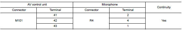
- Check continuity between AV control unit connector M101 and ground.
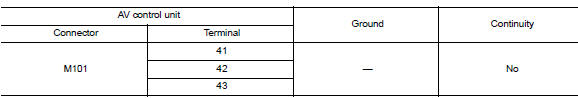
Is inspection result normal? YES >> GO TO 2.
NO >> Repair or replace harness or connectors.
2.Check microphone vcc voltage
- Connect AV control unit connector M101.
- Turn ignition switch on.
- Check voltage between terminals of av control unit connector m101.
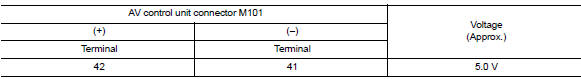
Is the inspection result normal? Yes >> go to 3.
No >> replace av control unit. Refer to av-406, "removal and installation".
3.Check microphone signal
- Connect microphone connector.
- Check signal between terminals of AV control unit connector M101.
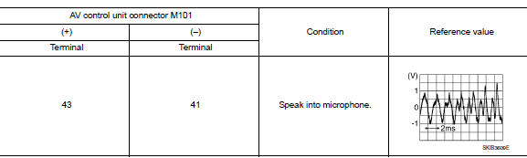
Is the inspection result normal? Yes >> replace av control unit. Refer to av-406, "removal and installation".
No >> replace microphone. Refer to av-421, "removal and installation".
Steering switch
Diagnosis procedure
Regarding wiring diagram information, refer to av-331, "wiring diagram".
1.Check steering wheel audio control switch resistance
- Turn ignition switch OFF.
- Disconnect combination switch (spiral cable) connector M79.
- Check resistance between the terminals of combination switch (spiral cable) connector m79.
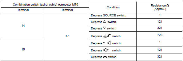
Is the inspection result normal? Yes >> go to 2.
No >> replace steering switches. Refer to av-411, "removal and installation".
2.Check combination switch (spiral cable)
Check continuity between combination switch (spiral cable) connectors m79 and m80.
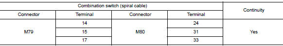
Is the inspection result normal? YES >> GO TO 3.
NO >> Replace combination switch (spiral cable). Refer to SR-16, "Removal and Installation".
3.Check harness between combination switch (spiral cable) and av control uint
- Disconnect AV control unit connector M100.
- Check continuity between combination switch (spiral cable) connector M80 and AV control unit connector M100.
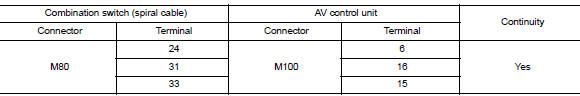
- Check continuity between combination switch (spiral cable) connector m80 and ground.
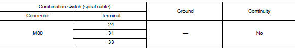
Is the inspection result normal? Yes >> replace av control unit. Refer to av-406, "removal and installation".
No >> repair or replace harness or connectors.
Usb connector
Diagnosis procedure
Regarding wiring diagram information, refer to av-331, "wiring diagram".
1.Check usb interface harness continuity
- Turn ignition switch off.
- Disconnect AV control unit connector M114 and USB interface connector M132.
- Check continuity between av control unit connector m114 and usb interface connector m132.
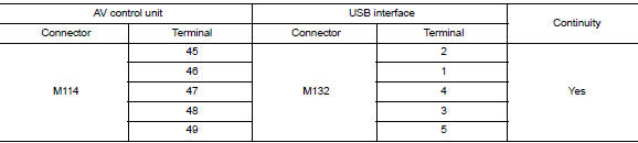
- Check continuity between av control unit connector m131 and ground.
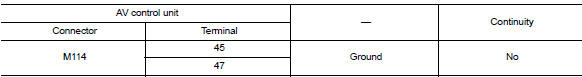
Is the inspection result normal? YES >> Replace the USB interface. Refer to AV-416, "Removal and Installation".
NO >> Repair or replace harness or connectors.
Auxiliary input jack
Diagnosis procedure
Regarding wiring diagram information, refer to av-331, "wiring diagram".
1.Check aux jack harness continuity
- Turn ignition switch off.
- Disconnect av control uint connector m101 and aux jack connector m133.
- Check continuity between av control uint connector m101 and aux jack connector m133.
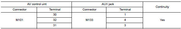
- Check continuity between av control uint connector m101 and ground.
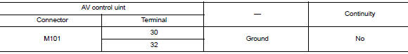
Is the inspection result normal? Yes >> replace the aux jack. Refer to av-416, "removal and installation".
No >> repair or replace harness or connectors.
 Dtc/circuit diagnosis
U1000 can comm circuit
DTC Logic
Dtc detection logic
Consult display
Dtc detection condition
Possible cause
Can comm circuit
[u1000]
Av control unit is not transmitting ...
 Symptom diagnosis
Multi av system
Symptom table
Related to audio
Related to hands-free phone
Before performing diagnosis, confirm that the cellular phone being used
by the customer is compatible w ...
Other materials:
System description
Component parts
Component parts location
Front tweeter LH
Steering switches
Audio unit
Front tweeter RH
Microphone
Front door speaker LH
Front door speaker RH
Rear door speaker LH
Rear door speaker RH
Rear woofer RH
Rear woofer LH
Antenna amp.
Satellite antenna
Win ...
Wheel side
WHEEL SIDE : Removal and Installation
REMOVAL
Remove the wheel and tire using power tool. Refer to WT-47, "Exploded
View".
Remove the brake caliper torque member bolts, leaving the brake hose
attached. Position the brake caliper
aside with wire. Refer to BR-41, "BRAKE C ...
Diagnosis system (ipdm e/r) (with intelligent key system)
Diagnosis Description
AUTO ACTIVE TEST
Description
In auto active test, the IPDM E/R sends a drive signal to the following
systems to check their operation.
Front wiper (LO, HI)
Parking lamp
License plate lamp
Tail lamp
Front fog lamp (if equipped)
Headlamp (LO, HI)
A/C compres ...
