Nissan Sentra Service Manual: Wheel side
WHEEL SIDE : Removal and Installation
REMOVAL
- Remove the wheel and tire using power tool. Refer to WT-47, "Exploded View".
- Remove the brake caliper torque member bolts, leaving the brake hose attached. Position the brake caliper aside with wire. Refer to BR-41, "BRAKE CALIPER ASSEMBLY : Removal and Installation".
CAUTION:
Do not depress the brake pedal while the brake caliper is removed.
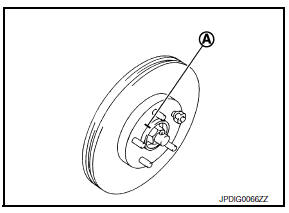
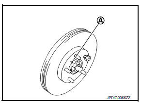
- Put alignment marks (A) on the disc brake rotor and on the wheel hub and bearing. Remove the disc brake rotor.
CAUTION:
Do not drop the disc brake rotor.
- Remove the wheel sensor bolt. Position the wheel sensor and the wheel sensor harness aside. Refer to BRC-106, "FRONT WHEEL SENSOR : Removal and Installation".
- Remove the cotter pin from the drive shaft.
- Remove the nut retainer from the wheel hub lock nut.
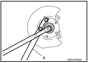
- Hold the wheel hub and bearing using Tool (A). Loosen the wheel hub lock nut.
Tool number (A): KV40104000 ( — )
- Using a piece of wood and a suitable tool, tap on the wheel hub lock nut to disengage the drive shaft from the wheel hub and bearing.
CAUTION:
- Do not place the drive shaft joint at an extreme angle.
Also be careful not to overextend slide joint.
- Do not allow the drive shaft to hang down without support.
NOTE:
Use a suitable puller if the drive shaft cannot be separated from the wheel hub and bearing even after performing the above procedure.
- Remove the wheel hub lock nut.
- Remove the nut and bolt from the lower ball joint. Disconnect the steering knuckle from the transverse link.
- Remove the drive shaft from the wheel hub and bearing.
- Remove the boot bands.
- Separate the boot from the joint sub-assembly.
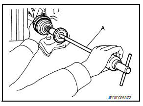
- Screw a suitable tool (A) into the joint sub-assembly screw part to a length of 30 mm (1.18 in) or more. Support the drive shaft with one hand and pull out the joint sub-assembly from the shaft.
CAUTION:
- Align the suitable tool and the drive shaft. Remove the joint sub-assembly by pulling firmly and uniformly.
- If the joint sub-assembly cannot be pulled out, try after removing the drive shaft from the vehicle. Refer to FAX- 30, "6M/T : Disassembly and Assembly (LH)".
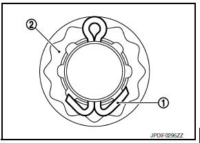
- Remove the circular clip (1) from the shaft.
- Remove the outer boot from the shaft.
INSTALLATION
- Clean the old grease from the joint sub-assembly using paper waste.
- Fill the serration slot on the joint sub-assembly (1) with NISSAN genuine grease or equivalent until the serration slot and ball groove become full to the brim.
CAUTION:
After applying the grease, use paper waste to wipe off the grease that has oozed out.
NOTE:
Always check with the Parts Department for the latest parts information.
- Install the outer boot and the boot bands to the shaft.
CAUTION:
- Wrap the serration on the shaft with tape to protect the boot from damage.
- Do not reuse the boot.
- Do not reuse the boot bands.
- Remove the tape wrapped around the serration on the shaft.
- Position the circular clip (1) on the groove at the shaft edge.
CAUTION:
Do not reuse the circular clip.
NOTE:
A drive joint inserter is recommended when installing the circular clip.
- Align with the shaft and the joint sub-assembly. Assemble the shaft with the joint sub-assembly while holding the circular clip.
- Install the joint sub-assembly (1) to the shaft using a suitable tool.
CAUTION:
- Make sure the circular clip is properly positioned on the groove of the joint sub-assembly.
- Confirm that the joint sub-assembly is correctly engaged while rotating the drive shaft.
- Apply the specified amount of grease to the inside of the large diameter side of the boot.
NOTE:
Always check with the Parts Department for the latest parts information.
Grease amount : Refer to FAX-49, "Drive Shaft".
- Install the boot securely into the grooves (indicated by “*” marks) as shown.
CAUTION:
If there is grease on the boot mounting surfaces (indicated by “*” marks) on the shaft or the joint sub-assembly, the boot may come off. Remove all grease from the boot mounting surfaces.
- To prevent the deformation of the boot, adjust the boot installation length to the specified value by inserting a suitable tool into the inside of the boot from the large diameter side of the boot and discharging the inside air.
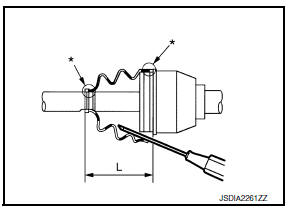
Boot installation length (L) : Refer to FAX-49, "Drive Shaft".
CAUTION:
- The boot may break if the boot installation length is not correct.
- Be careful not to touch the inside of the boot with the tip of the suitable tool.
- Install new large and small boot bands securely using Tool (A).
CAUTION:
Do not reuse the boot bands.
Tool number (A): KV40107300 ( – )
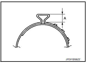
- Secure the boot band so that dimension (A) meets the specification.
Dimension (A) : Refer to FAX-49, "Drive Shaft".
- Attempt to rotate the boot to check whether or not the boot bands are securing the boot. If the boot is not secure, remove the boot bands, reposition the boot, and install new boot bands.
- Clean the mating surfaces of the wheel hub lock nut and the wheel hub assembly.
CAUTION:
Do not apply lubricating oil to these mating surfaces.
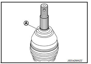
- Clean the mating surfaces of the joint sub-assembly and the wheel hub and bearing. Apply Molykote M77 lubricant to the surface (A) of the joint sub-assembly.
CAUTION:
Apply lubricant to cover the entire flat mating surface of the joint sub-assembly.
NOTE:
Always check with the Parts Department for the latest parts information.
Amount of lubricant : Refer to FAX-49, "Drive Shaft"
- Install the drive shaft to the wheel hub and bearing. Temporarily install, but do not tighten, the wheel hub lock nut.
- Install the transverse link to the steering knuckle with the nut and bolt. Refer to FAX-8, "Exploded View".
- Hold the wheel hub and bearing using Tool. Tighten the wheel hub lock nut.
CAUTION:
- Since the drive shaft is assembled by press-fitting, use a torque wrench to tighten the wheel hub lock nut. Do not use a power tool.
- Too much torque causes axle noise. Too little torque causes wheel bearing looseness. Tighten the wheel hub lock nut to the specification.
Tool number (A): KV40104000 ( — )
- Install the nut retainer (2).
- Install the cotter pin (1). Securely bend the cotter pin to prevent rattles.
CAUTION:
Do not reuse the cotter pin.
- Install the wheel sensor, the wheel sensor bolt, and the wheel sensor harness. Refer to BRC-106, "FRONT WHEEL SENSOR : Removal and Installation".
- Align the matching marks (A) on the disc brake rotor and on the wheel hub and bearing. Install the disc brake rotor.
CAUTION:
Do not drop the disc brake rotor.
- Remove the wire from the brake caliper. Install the brake caliper and the brake caliper torque member bolts. Refer to BR-41, "BRAKE CALIPER ASSEMBLY : Removal and Installation".
CAUTION:
Do not twist the brake hose.
- Install the wheel and tire. Refer to WT-47, "Adjustment".
- Complete the inspection. Refer to FAX-17, "Inspection".
 Front drive shaft boot
Exploded View
(LH)
Circular clip
Dust shield
Slide joint housing
Snap ring
Spider assembly
Boot band
Boot
Shaft
Damper band
Dynamic damper
Circular clip
Joint sub-assembly ...
 Transaxle side
TRANSAXLE SIDE : Removal and Installation
Remove boot after drive shaft is removed from the vehicle.
For drive shaft removal and installation, follow the instructions bellow.
6M/T: Refer to FAX ...
Other materials:
Power outlet
Center Console
Console Box (if so equipped)
The power outlets are for powering electrical
accessories such as cellular telephones. They
are rated at 12 volt, 120W (10A) maximum.
The power outlets are powered only when the
ignition switch is in the ACC or ON position.
CAUTION
The ...
Tow Truck Towing
NISSAN recommends that vehicle be towed with driving (front) wheels off the
ground or that a dolly be used.
CVT: Continuously Variable Transmission
M/T: Manual transmission
CAUTION:
All applicable state or Provincial laws and local laws regarding
the towing operation must be ...
When reading the manual
This manual includes information for all features
and equipment available on this model. Features
and equipment in your vehicle may vary depending
on model, trim level, options selected, order,
date of production, region or availability. Therefore,
you may find information about features or
eq ...
