Nissan Sentra Service Manual: Dtc/circuit diagnosis
U1000 can comm circuit
DTC Logic
Dtc detection logic
| Consult display | Dtc detection condition | Possible cause |
| Can comm circuit [u1000] | Av control unit is not transmitting or receiving can communication signal for 2 seconds or more. | CAN communication system. |
Diagnosis Procedure
1.Perform self diagnostic result
- Turn ignition switch on and wait for 2 seconds or more.
- Perform self diagnostic result for multi av.
Is can comm circuit displayed? Yes >> refer to lan-16, "trouble diagnosis flow chart".
No >> refer to gi-39, "intermittent incident".
U1010 control unit (can)
Dtc logic
Dtc detection logic
| Consult display | Dtc detection condition | Possible cause |
| Control unit (can) [u1010] | Error during CAN controller hardware initialization (VCAN). | Replace the av control unit if the malfunction occurs
constantly.
Refer to av-406, "removal and installation". |
U1217 av control unit
Dtc logic
Dtc detection logic
| Consult display | Dtc detection condition | Possible cause |
| Bluetooth module [u1217] | Connection failure to the internal blueoothВ® sub unit is detected. | Replace AV control unit if malfunction occurs
constantly.
Refer to AV-406, "Removal and Installation". |
U1229 av control unit
Dtc logic
Dtc detection logic
| Consult display | Dtc detection condition | Possible cause |
| iPod CERTIFICATION [U1229] | Ipod authentication chip error. | Replace av control unit if malfunction occurs
constantly.
Refer to av-406, "removal and installation". |
U122f av control unit
Dtc logic
Dtc detection logic
| Consult display | Dtc detection condition | Possible cause |
| Digital broadcasting connection error [u122f] | Communication error with digital audio broadcast module internal to AV control unit. | Replace av control unit if malfunction occurs
constantly.
Refer to av-406, "removal and installation". |
U1244 gps antenna
Dtc logic
Dtc detection logic
| Consult display | Dtc detection condition | Possible cause |
| Gps antenna conn [u1244] | Open or short to ground is detected in gps antenna connection. |
|
Diagnosis procedure
Regarding wiring diagram information, refer to av-331, "wiring diagram".
1.Gps antenna inspection
Visually inspect the gps antenna and antenna feeder. Refer to av-412, "location of antenna".
Is inspection result normal? Yes >> go to 2.
No >> repair or replace malfunctioning components.
2.Check av control unit voltage
- Turn ignition switch on.
- Check voltage between av control unit connector m116 terminal 50 and ground.
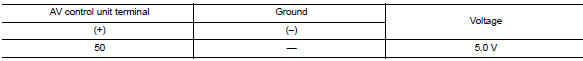
Is inspection result normal? YES >> Replace GPS antenna. Refer to AV-420, "Removal and Installation".
NO >> Replace AV control unit. Refer to AV-406, "Removal and Installation".
U1258 satellite radio antenna
DTC Lo
gic
Dtc detection logic
| Consult display | Dtc detection condition | Possible cause |
| Xm antenna conn [u1258] | Open or short to ground is detected in satellite antenna connection. |
|
Diagnosis Procedure
1.Satellite antenna inspection
Visually inspect the satellite antenna and antenna feeder. Refer to AV-412, "Location of Antenna".
Is inspection result normal? YES >> GO TO 2.
NO >> Repair or replace malfunctioning components.
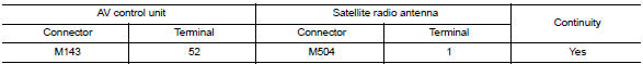
2.Check satellite antenna feeder continuity
- Disconnect AV control unit connector M143 and satellite radio antenna connector M504.
- Check continuity between av control unit connector m143 and satellite radio antenna connector m504.
- Check continuity between av control unit connector m143 and ground.
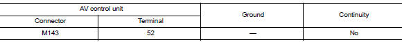
Is the inspection result normal? Yes >> go to 3
No >> repair or replace harness or connectors.
3.Check av control unit voltage
- Connect av control unit connector m143.
- Turn ignition switch ON.
- Check voltage between av control unit connector m143 terminal 52 and ground.
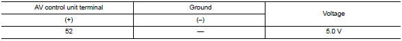
Is inspection result normal? Yes >> replace satellite radio antenna. Refer to av-419, "removal and installation".
No >> replace av control unit. Refer to av-406, "removal and installation".
U1263 usb
Dtc logic
Dtc detection logic
| Consult display | Dtc detection condition | Possible cause |
| Usb overcurrent [u1263] | Overcurrent in usb harness is detected. |
|
Dtc confirmation procedure
1.Perform self diagnostic result
- If there is a device connected to the usb interface, disconnect it.
- Turn ignition switch on and wait for 2 seconds or more.
- Perform Self Diagnostic Result for MULTI AV.
Is DTC U1263 displayed? YES >> Refer to AV-359, "Diagnosis Procedure".
NO >> Inspection End.
Diagnosis procedure
1.Check usb interface harness
Visually inspect usb interface harness. Refer to av-416, "removal and installation".
Is the inspection result normal? Yes >> go to 2.
No >> replace usb interface harness. Refer to av-416, "removal and installation".
2.Check usb interface harness
Check usb interface harness. Refer to av-391, "diagnosis procedure".
Is the inspection result normal? Yes >> replace av control unit. Refer to av-406, "removal and installation".
No >> replace usb interface harness. Refer to av-416, "removal and installation".
U1264 antenna amp
Dtc logic
Dtc detection logic
| Consult display | Dtc detection condition | Possible cause |
| ANTENNA AMP TERMINAL [U1264] | Open or short to ground is detected in antenna amp. Connection. |
|
Diagnosis procedure
Regarding Wiring Diagram information, refer to AV-331, "Wiring Diagram".
1.Antenna amp. Inspection
Visually inspect the antenna amp. And antenna feeder. Refer to av-412, "location of antenna".
Is inspection result normal? Yes >> go to 2.
No >> repair or replace malfunctioning components.
2.Check continuity between av control unit and antenna amp.
- Turn ignition switch off.
- Disconnect av control unit connector m145 and antenna amp. Connector m502.
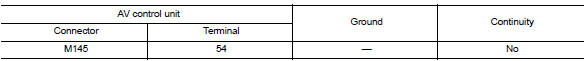
- Check continuity between av control unit connector m145 and antenna amp. Connector m502.

- Check continuity between av control unit connector m145 and ground.
Is the inspection result normal? Yes >> go to 2.
No >> repair or replace harness or connectors.
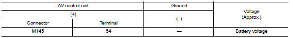
3.Check av control unit voltage
- Connect av control unit connector m145.
- Turn ignition switch ON.
- Check voltage between av control unit connector m145 and ground.
Is the inspection result normal? Yes >> replace antenna amp. Refer to av-419, "removal and installation".
No >> replace av control unit. Refer to av-406, "removal and installation".
Is the inspection result normal? Yes >> replace antenna amp. Refer to av-419, "removal and installation".
No >> replace av control unit. Refer to av-406, "removal and installation".
U1265 bose amp
DTC Logic
| Consult display | Dtc detection condition | Possible cause |
| Amp on terminal [u1265] | Open or short to ground is detected in bose amp. On signal circuit. | Open or short to ground in bose amp. On signal circuit. |
Diagnosis Procedure
Regarding Wiring Diagram information, refer to AV-331, "Wiring Diagram".
1.Check continuity between av control unit and bose speaker amp.
- Turn ignition switch off.
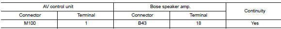
- Disconnect av control unit connector m100 and bose speaker amp. Connector b43.
- Check continuity between av control unit connector m100 and bose speaker amp. Connector b43.
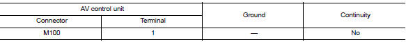
- Check continuity between av control unit connector m100 and ground.
Is the inspection result normal? Yes >> go to 2.
No >> repair or replace harness or connectors.
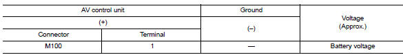
2.Check av control unit voltage
- Connect AV control unit connector M100.
- Turn ignition switch ON.
- Check voltage between av control unit connector m100 and ground.
Is the inspection result normal? Yes >> go to 2.
No >> repair or replace harness or connectors.
2.Check av control unit voltage
- Connect AV control unit connector M100.
- Turn ignition switch on.
- Check voltage between av control unit connector m100 and ground.
Is the inspection result normal? YES >> Replace Bose speaker amp. Refer to AV-417, "Removal and Installation".
NO >> Replace AV control unit. Refer to AV-406, "Removal and Installation".
U12aa configuration error
Dtc logic
Dtc detection logic
| Consult display | Dtc detection condition | Possible cause |
| Configuration Error [U12AA] | Av control unit is not properly configured or configuration is corrupt. | Configuration data needs to be written.
Refer to AV-350, "CONFIGURATION (AV CONTROL UNIT) : Work Procedure". |
Diagnosis procedure
1.Perform configuration
When u12aa is detected, configuration data must be written.
>> Write configuration data with consult. Refer to av-350, "configuration (av control unit) : work procedure".
U12ac av control unit
Dtc logic
Dtc detection logic
| Consult display | Dtc detection condition | Possible cause |
| Display Temperature too High [U12AC] | Display temperature has exceeded maximum temperature. Display is switched off to avoid irreversible damage. | Replace av control unit if malfunction occurs
constantly.
Refer to av-406, "removal and installation". |
U12ad av control unit
DTC Logic
Dtc detection logic
| Consult display | Dtc detection condition | Possible cause |
| Ecu temperature too high [u12ad] | Av control unit temperature has exceeded maximum temperature. | Replace AV control unit if malfunction occurs
constantly.
Refer to AV-406, "Removal and Installation". |
U12ae av control unit
DTC Logic
Dtc detection logic
| Consult display | Dtc detection condition | Possible cause |
| Internal amplifier temperature warning [u12ae] | Internal amplifier temperature has exceeded maximum temperature. | Replace av control unit if malfunction occurs
constantly.
Refer to av-406, "removal and installation". |
U12af av control unit
Dtc logic
Dtc detection logic
| Consult display | Dtc detection condition | Possible cause |
| CD Mechanism Temperature Warning [U12AF] | Cd drive temperature has exceeded maximum temperature. Cd drive is switched off to avoid irreversible damage. | Replace av control unit if malfunction occurs
constantly.
Refer to av-406, "removal and installation". |
U12b0 power supply voltage
Dtc logic
Dtc detection logic
| Consult display | Dtc detection condition | Possible cause |
| Supply voltage goes below 9v > 20s [u12b0] | Av control unit supply voltage exceeds lower limits. |
|
Diagnosis procedure
1.Check charging system
Check the vehicle charging system. Refer to chg-14, "work flow (with exp-800 ni or gr8-1200 ni)" or chg-17, "work flow (without exp-800 ni or gr8-1200 ni)".
Is the inspection result normal? Yes >> go to 2.
No >> repair or replace the malfunctioning components.
2.Check av control unit power supply and ground circuits
Perform the AV control unit power supply and ground circuit diagnosis procedure. Refer to AV-370, "AV CONTROL UNIT : Diagnosis Procedure".
Is the inspection result normal? YES >> Replace the AV control unit. Refer to AV-406, "Removal and Installation".
NO >> Repair or replace harness or connectors.
U12b1 power supply voltage
Dtc logic
Dtc detection logic
| Consult display | Dtc detection condition | Possible cause |
| Supply voltage goes high > 16v for 20s [u12b1] | Av control unit supply voltage exceeds upper limits. | Charging system malfunction. |
Diagnosis procedure
1.Check charging system
Check the vehicle charging system. Refer to chg-14, "work flow (with exp-800 ni or gr8-1200 ni)" or chg-17, "work flow (without exp-800 ni or gr8-1200 ni)".
Is the inspection result normal? Yes >> replace the av control unit. Refer to av-406, "removal and installation".
No >> repair or replace the malfunctioning components.
U1310 av control unit
Dtc logic
Dtc detection logic
| Consult display | Dtc detection condition | Possible cause |
| CONTROL UNIT (AV) [U1310] | Error during CAN controller hardware initialization (MCAN). | Replace av control unit if malfunction occurs
constantly.
Refer to av-406, "removal and installation". |
 Basic inspection
Diagnosis and repair workflow
Work flow
OVERALL SEQUENCE
DETAILED FLOW
1.GET INFORMATION FOR SYMPTOM
Get detailed information from the customer about the symptom (the condition
and the envi ...
 Power supply and ground circuit
Av control unit
Av control unit : diagnosis procedure
Regarding wiring diagram information, refer to av-331, "wiring diagram".
1.Check fuse
Check that the following fuses are not blown.
...
Other materials:
M&A branch line circuit
Diagnosis procedure
1.Check connector
Turn the ignition switch off.
Disconnect the battery cable from the negative terminal.
Check the terminals and connectors of the combination meter for damage,
bend and loose connection
(unit side and connector side).
Is the inspection result nor ...
Throttle valve closed position
learning
Description
Throttle Valve Closed Position Learning is a function of ECM to learn the
fully closed position of the throttle
valve by monitoring the throttle position sensor output signal. It must be
performed each time the harness connector
of the electric throttle control actuator or ECM is ...
Precaution for work
When removing or disassembling each component, be careful not to damage
or deform it. If a component
may be subject to interference, be sure to protect it with a shop cloth.
When removing (disengaging) components with a screwdriver or similar
tool, be sure to wrap the component
with a ...
