Nissan Sentra Service Manual: P0850 PNP Switch
Description
For CVT models, transmission range switch is turn ON when the selector lever is P or N.
For M/T models, park/neutral position (PNP) range switch is ON when the selector lever is Neutral position.
ECM detects the position because the continuity of the line (the ON) exists.
DTC Logic
DTC DETECTION LOGIC
| DTC No. | CONSULT screen terms (Trouble diagnosis content) | DTC detecting condition | Possible cause |
| P0850 | P-N POS SW/CIRCUIT (Park/Neutral switch input circuit) |
|
|
DTC CONFIRMATION PROCEDURE
1.PRECONDITIONING
If DTC Confirmation Procedure has been previously conducted, always perform the following procedure before conducting the next test.
- Turn ignition switch OFF and wait at least 10 seconds.
- Turn ignition switch ON.
- Turn ignition switch OFF and wait at least 10 seconds.
>> GO TO 2.
2.PERFORM COMPONENT FUNCTION CHECK
Perform component function check. Refer to EC-356, "Component Function Check".
Is the inspection result normal? YES >> GO TO 3.
NO >> Proceed to EC-356, "Diagnosis Procedure".
3.PERFORM DTC CONFIRMATION PROCEDURE
 With CONSULT
- Select “DATA MONITOR” mode of “ENGINE” using CONSULT.
- Start engine and warm it up to normal operating temperature.
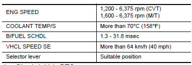
- Maintain the following conditions for at least 60 consecutive seconds.
CAUTION:
Always drive vehicle at a safe speed.
- Check 1st trip DTC.
 With GST
Follow the procedure “With CONSULT” above.
Is 1st trip DTC detected? YES >> Proceed to EC-356, "Diagnosis Procedure".
NO >> INSPECTION END
Component Function Check
1.CHECK PNP SIGNAL FUNCTION
 With CONSULT
- Turn ignition switch ON.
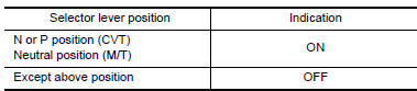
- Select “P/N POSI SW” in “DATA MONITOR” mode of “ENGINE” using CONSULT. Then check the “P/N POSI SW” signal as per the following conditions.
Is the inspection result normal? YES >> GO TO 2.
NO >> Proceed to EC-356, "Diagnosis Procedure".
2.PERFORM COMPONENT FUNCTION CHECK
- Turn ignition switch ON.
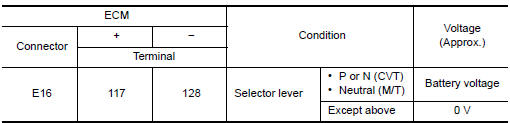
- Check the voltage between ECM harness connector and ground as per the following conditions.
Is the inspection result normal? YES >> INSPECTION END
NO >> Proceed to EC-356, "Diagnosis Procedure".
Diagnosis Procedure
1.INSPECTION START
Check which type of transmission the vehicle is equipped with.
Which type of transmission? CVT models>>GO TO 2.
M/T models>>GO TO 6.
2.CHECK TRANSMISSION RANGE SWITCH POWER SUPPLY
- Turn ignition switch OFF.
- Disconnect transmission range switch harness connector.
- Turn ignition switch ON.
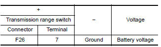
- Check the voltage between transmission range switch harness connector and ground.
Is the inspection result normal? YES >> GO TO 4.
NO >> GO TO 3.
3.CHECK TRANSMISSION RANGE SWITCH POWER SUPPLY CIRCUIT
- Turn ignition switch OFF.
- Disconnect IPDM E/R harness connector.
- Check the continuity between transmission range switch harness connector and IPDM E/R harness connector.
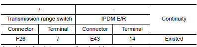
- Also check harness for short to ground.
Is the inspection result normal? YES >> Perform the trouble diagnosis for power supply circuit.
NO >> Repair or replace error-detected parts.
4.CHECK TRANSMISSION RANGE SWITCH SIGNAL CIRCUIT
- Turn ignition switch OFF.
- Disconnect ECM harness connector.
- Check the continuity between transmission range switch harness connector and ECM harness connector.
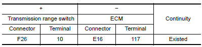
- Also check harness for short to ground and to power.
Is the inspection result normal? YES >> GO TO 5.
NO >> Repair or replace error-detected parts.
5.CHECK TRANSMISSION RANGE SWITCH
Check the transmission range switch. Refer to TM-165, "Component Inspection".
Is the inspection result normal? YES >> Check intermittent incident. Refer to GI-39, "Intermittent Incident".
NO >> Replace transaxle assembly. Refer to TM-283, "Removal and Installation".
6.CHECK PARK/NEUTRAL POSITION (PNP) SWITCH POWER SUPPLY
- Turn ignition switch OFF.
- Disconnect PNP switch harness connector
- Turn ignition switch ON.
- Check the voltage between PNP switch harness connector and ground.
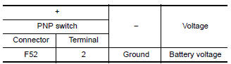
Is the inspection result normal? YES >> GO TO 7.
NO >> Perform the trouble diagnosis for power supply circuit.
7.CHECK PNP SWITCH INPUT SIGNAL CIRCUIT
- Turn ignition switch OFF.
- Disconnect ECM harness connector
- Check the continuity between PNP switch harness connector and ECM harness connector.
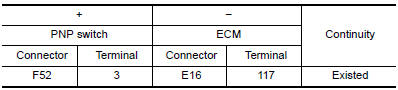
- Also check harness for short to ground and to power.
Is the inspection result normal? YES >> GO TO 8.
NO >> Repair or replace error-detected parts.
8.CHECK PNP SWITCH
Check the PNP switch. Refer to TM-17, "PARK/NEUTRAL POSITION (PNP) SWITCH : Component Inspection".
Is the inspection result normal? YES >> Check intermittent incident. Refer to GI-39, "Intermittent Incident".
NO >> Replace PNP switch. Refer to TM-21, "Removal and Installation".
 P0643 Sensor power supply
Description
ECM supplies a voltage of 5.0 V to some of the sensors systematically divided
into 2 groups, respectively.
Accordingly, when a short circuit develops in a sensor power source, a
ma ...
 P1078 EVT Control position sensor
DTC Logic
DTC DETECTION LOGIC
DTC No.
CONSULT screen terms
(Trouble diagnosis content)
DTC detecting condition
Possible cause
P1078
EXH TIM SEN/CIRC-B1
(Exhaust val ...
Other materials:
P0715 Input speed sensor A
DTC Logic
DTC DETECTION LOGIC
DTC
CONSULT screen terms
(Trouble diagnosis content)
DTC detection condition
Possible causes
P0715
INPUT SPEED SENSOR A
(Input/Turbine Speed Sensor
A Circuit)
The primary speed sensor value is less than
150 r ...
Headlamp (hi) circuit
Description
The IPDM E/R (intelligent power distribution module engine room) controls the
headlamp high relay based on
inputs from the BCM over the CAN communication lines. When the headlamp high
relay is energized, power
flows through fuses 41 and 42, located in the IPDM E/R. Power then flo ...
Symptom diagnosis
Door does not lock/unlock with door lock and unlock switch
All door
ALL DOOR : Description
All doors do not lock/unlock using door lock and unlock switch.
ALL DOOR : Diagnosis Procedure
1.CHECK DOOR LOCK AND UNLOCK SWITCH
Check door lock and unlock switch.
Refer to DLK-97, "Component F ...
