Nissan Sentra Service Manual: P1078 EVT Control position sensor
DTC Logic
DTC DETECTION LOGIC
| DTC No. | CONSULT screen terms (Trouble diagnosis content) | DTC detecting condition | Possible cause |
| P1078 | EXH TIM SEN/CIRC-B1 (Exhaust valve timing control position sensor circuit bank 1) | An excessively high or low voltage from the sensor is sent to ECM. |
|
DTC CONFIRMATION PROCEDURE
1.PRECONDITIONING
If DTC Confirmation Procedure has been previously conducted, always perform the following procedure before conducting the next test.
- Turn ignition switch OFF and wait at least 10 seconds.
- Turn ignition switch ON.
- Turn ignition switch OFF and wait at least 10 seconds.
>> GO TO 2.
2.PERFORM DTC CONFIRMATION PROCEDURE
- Start engine and let it idle for 10 seconds.
- Check 1st trip DTC.
Is 1st trip DTC detected? YES >> Proceed to EC-359, "Diagnosis Procedure".
NO >> INSPECTION END
Diagnosis Procedure
1.CHECK EXHAUST VALVE TIMING (EVT) CONTROL POSITION SENSOR POWER SUPPLY
- Turn ignition switch OFF.
- Disconnect exhaust valve timing (EVT) control position sensor harness connector.
- Turn ignition switch ON.
- Check the voltage between EVT control position sensor harness connector and ground.
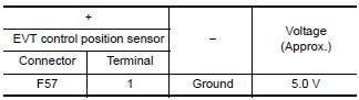
Is the inspection result normal? YES >> GO TO 3.
NO >> GO TO 2.
2.CHECK SENSOR POWER SUPPLY 2 CIRCUIT
Check sensor power supply 2 circuit. Refer to EC-444, "Diagnosis Procedure".
Is inspection result normal? YES >> Perform the trouble diagnosis for power supply circuit.
NO >> Repair or replace error-detected parts.
3.CHECK EVT CONTROL POSITION SENSOR GROUND CIRCUIT
- Turn ignition switch OFF.
- Disconnect ECM harness connector
- Check the continuity between EVT control position sensor harness connector and ECM harness connector.
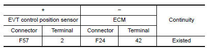
- Also check harness for short to power.
Is the inspection result normal? YES >> GO TO 4.
NO >> Repair or replace error-detected parts.
4.CHECK EVT CONTROL POSITION SENSOR INPUT SIGNAL CIRCUIT
- Disconnect ECM harness connector.
- Check the continuity between EVT control position sensor harness connector and ECM harness connector.
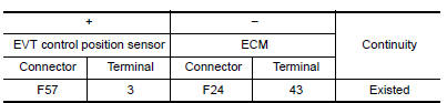
- Also check harness for short to ground and to power.
Is the inspection result normal? YES >> GO TO 5.
NO >> Repair or replace error-detected parts.
5.CHECK EVT CONTROL POSITION SENSOR
Check the EVT control position sensor. Refer to EC-360, "Component Inspection (EVT Control Position Sensor)".
Is the inspection result normal? YES >> GO TO 6.
NO >> Replace EVT control position sensor. Refer to EM-60, "Removal and Installation".
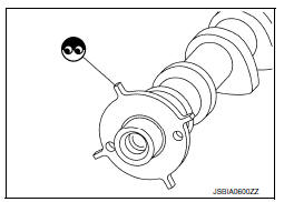
6.CHECK CAMSHAFT (EXT)
Check the following.
- Accumulation of debris to the signal plate of camshaft rear end
- Chipping signal plate of camshaft rear end
Is the inspection result normal? YES >> Check intermittent incident. Refer to GI-39, "Intermittent Incident".
NO >> Remove debris and clean the signal plate of camshaft rear end or replace camshaft. Refer to EM-60, "Removal and Installation".
Component Inspection (EVT Control Position Sensor)
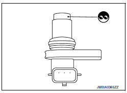
1.EXHAUST VALVE TIMING (EVT) CONTROL POSITION SENSOR-1
- Turn ignition switch OFF.
- Disconnect EVT control position sensor harness connector.
- Loosen the fixing bolt of the sensor.
- Remove EVT control position sensor.
- Visually check the sensor for chipping.
Is the inspection result normal? YES >> GO TO 2.
NO >> Replace EVT control position sensor. Refer to EM-60, "Removal and Installation".
2.EVT CONTROL POSITION SENSOR-2
Check resistance EVT control position sensor terminals as shown below.
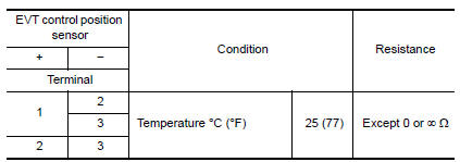
Is the inspection result normal? YES >> INSPECTION END
NO >> Replace EVT control position sensor. Refer to EM-60, "Removal and Installation".
 P0850 PNP Switch
Description
For CVT models, transmission range switch is turn ON when the selector lever
is P or N.
For M/T models, park/neutral position (PNP) range switch is ON when the selector
lever is Ne ...
 P1148 Closed loop control
DTC Logic
DTC DETECTION LOGIC
NOTE:
DTC P1148 is displayed with DTC for A/F sensor 1.
When the DTC is detected, perform the trouble diagnosis of DTC corresponding to
A/F sensor 1.
DTC ...
Other materials:
Rearview mirror (if so equipped)
The night position 1 reduces glare from the
headlights of vehicles behind you at night.
Use the day position 2 when driving in daylight
hours.
WARNINGUse the night position only when
necessary,
because it reduces rear view clarity.
...
Emission control information label
The emission control information label is attached
to the underside of the hood as shown.
Tire and loading information label
The cold tire pressure is shown on the Tire and
Loading Information label. The label is located as
shown.
Air conditioner specification label
The air condit ...
Front wiper drive assembly
Exploded view
Wiper blade (RH)
Wiper arm (RH)
Wiper drive assembly
Wiper arm (LH)
Wiper blade (LH)
Removal and installation
REMOVAL
Remove the cowl top. Refer to EXT-26, "Removal and Installation".
Disconnect the harness connector from the wiper drive assembly.
...
