Nissan Sentra Service Manual: P0441 EVAP Control system
DTC Logic
DTC DETECTION LOGIC
NOTE:
If DTC P0441 is displayed with other DTC such as P2122, P2123, P2127, P2128 or P2138, first perform trouble diagnosis for other DTC.
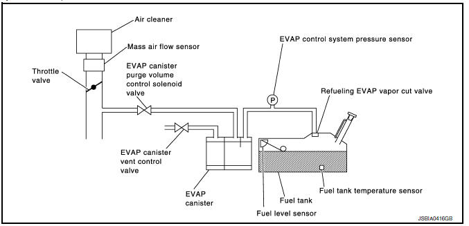
In this evaporative emission (EVAP) control system, purge flow occurs during non-closed throttle conditions.
Purge volume is related to air intake volume. Under normal purge conditions (non-closed throttle), the EVAP canister purge volume control solenoid valve is open to admit purge flow. Purge flow exposes the EVAP control system pressure sensor to intake manifold vacuum.
Under normal conditions (non-closed throttle), sensor output voltage indicates if pressure drop and purge flow are adequate. If not, a malfunction is determined.
| DTC No. | CONSULT screen terms (Trouble diagnosis content) | DTC detecting condition | Possible cause |
| P0441 | EVAP PURG FLOW/MON (Evaporative emission system incorrect purge flow) | EVAP control system does not operate properly, EVAP control system has a leak between intake manifold and EVAP control system pressure sensor |
|
DTC CONFIRMATION PROCEDURE
1.PRECONDITIONING
If DTC Confirmation Procedure has been previously conducted, always perform the following procedure before conducting the next test.
- Turn ignition switch OFF and wait at least 10 seconds.
- Turn ignition switch ON.
- Turn ignition switch OFF and wait at least 10 seconds.
Will CONSULT be used? YES >> GO TO 2.
NO >> GO TO 5.
2.PERFORM DTC CONFIRMATION PROCEDURE-1
 WITH CONSULT
TESTING CONDITION:
Always perform test at a temperature of 5В°C (41В°F) or more.
- Start engine and warm it up to normal operating temperature.
- Turn ignition switch OFF and wait at least 10 seconds.
- Turn ignition switch ON.
- Turn ignition switch OFF and wait at least 10 seconds.
- Start engine and let it idle for at least 70 seconds.
- Select “PURG FLOW P0441” of “EVAPORATIVE SYSTEM” in “DTC WORK SUPPORT” mode of “ENGINE” using CONSULT.
- Touch “START”.
Is “COMPLETED” displayed on CONSULT screen? YES >> GO TO 4.
NO >> GO TO 3.
3.PERFORM DTC CONFIRMATION PROCEDURE-2
When the following conditions are met, “TESTING” will be displayed on the CONSULT screen. Maintain the conditions continuously until “TESTING” changes to “COMPLETED”. (It will take at least 35 seconds.)
CAUTION:
Always drive vehicle at a safe speed.
NOTE:
If “TESTING” does not change for a long time, retry from step 2.
Is “COMPLETED” displayed on CONSULT screen? YES >> GO TO 4.
NO >> Perform DTC CONFIRMATION PROCEDURE again. GO TO 2.
4.PERFORM DTC CONFIRMATION PROCEDURE-3
Touch “SELF-DIAG RESULTS”.
Which is displayed on CONSULT screen? OK >> INSPECTION END
NG >> Proceed to EC-290, "Diagnosis Procedure".
5.PERFORM COMPONENT FUNCTION CHECK
 WITH GST
Perform component function check. Refer to EC-289, "Component Function Check".
NOTE:
Use component function check to check the overall monitoring function of the EVAP control system purge flow monitoring. During this check, a 1st trip DTC might not be confirmed.
Is the inspection result normal? YES >> INSPECTION END
NO >> Proceed to EC-290, "Diagnosis Procedure".
Component Function Check
1.PERFORM COMPONENT FUNCTION CHECK
- Lift up drive wheels.
- Start engine (VDC switch OFF) and warm it up to normal operating temperature.
- Turn ignition switch OFF and wait at least 10 seconds.
- Start engine and wait at least 70 seconds.
- Set voltmeter probes to ECM harness connector terminals as per the following.
*1: Except for California
*2: For California
- Check EVAP control system pressure sensor value at idle speed and note it.
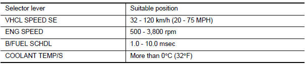
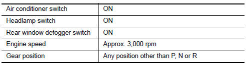
- Establish and maintain the following conditions for at least 1 minute.
- Verify that EVAP control system pressure sensor value stays 0.1 V less than the value at idle speed (measured at step 6) for at least 1 second.
Is the inspection result normal? YES >> INSPECTION END
NO >> Proceed to EC-290, "Diagnosis Procedure".
Diagnosis Procedure
1.CHECK EVAP CANISTER
- Turn ignition switch OFF.
- Check EVAP canister for cracks.
Is the inspection result normal? YES-1 >> With CONSULT: GO TO 2.
YES-2 >> Without CONSULT: GO TO 3.
NO >> Replace EVAP canister. Refer to FL-15, "Removal and Installation".
2.CHECK PURGE FLOW
 WITH CONSULT
- Disconnect vacuum hose connected to EVAP canister purge volume control solenoid valve at EVAP service port
- Start engine and let it idle.
- Select “PURG VOL CONT/V” in “ACTIVE TEST” mode of “ENGINE” using CONSULT.
- Touch “Qd” and “Qu” on CONSULT screen to adjust “PURG VOL CONT/V” opening and check vacuum existence.
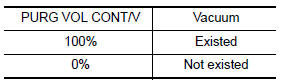
Is the inspection result normal? YES >> GO TO 7.
NO >> GO TO 4.
3.CHECK PURGE FLOW
 WITHOUT CONSULT
- Start engine and warm it up to normal operating temperature
- Stop engine
- Disconnect vacuum hose connected to EVAP canister purge volume control solenoid valve at EVAP service port and install vacuum gauge. For the location of EVAP service port, refer to EC-49, "EVAPORATIVE EMISSION SYSTEM : System Description".
- Start engine and let it idle.
Never depress accelerator pedal even slightly.
- Check vacuum gauge indication before 60 seconds pass after starting engine.
Vacuum should not exist.
- Rev engine up to 2,000 rpm after 100 seconds pass after starting engine.
Vacuum should exist.
Is the inspection result normal? YES >> GO TO 7.
NO >> GO TO 4.
4.CHECK EVAP PURGE LINE
- Turn ignition switch OFF.
- Check EVAP purge line for improper connection or disconnection.
Refer to EC-49, "EVAPORATIVE EMISSION SYSTEM : System Description".
Is the inspection result normal? YES >> GO TO 5.
NO >> Repair EVAP purge line.
5.CHECK EVAP PURGE HOSE AND PURGE PORT
- Disconnect purge hoses connected to EVAP service port
 and
and
EVAP canister purge volume control solenoid valve .
. - Blow air into each hose and EVAP purge port
 .
.
- Check that air flows freely.
Is the inspection result normal? YES-1 >> With CONSULT: GO TO 6.
YES-2 >> Without CONSULT: GO TO 7.
NO >> Repair or clean hoses and/or purge port.
6.CHECK EVAP CANISTER PURGE VOLUME CONTROL SOLENOID VALVE
 WITH CONSULT
- Start engine.
- Perform “PURG VOL CONT/V” in “ACTIVE TEST” mode of “ENGINE” using CONSULT. Check that engine speed varies according to the valve opening.
Does engine speed vary according to the valve opening? YES >> GO TO 8.
NO >> GO TO 7.
7.CHECK EVAP CANISTER PURGE VOLUME CONTROL SOLENOID VALVE
Check the EVAP canister purge volume control solenoid valve. Refer to EC-296, "Component Inspection".
Is the inspection result normal? YES >> GO TO 8.
NO >> Replace EVAP canister purge volume control solenoid valve. Refer to EM-27, "Exploded View".
8.CHECK EVAP CONTROL SYSTEM PRESSURE SENSOR CONNECTOR
- Disconnect EVAP control system pressure sensor harness connector.
- Check that water is not inside connectors.
Is the inspection result normal? YES >> GO TO 9.
NO >> Replace EVAP control system pressure sensor. Refer to FL-15, "Removal and Installation".
9.CHECK EVAP CONTROL SYSTEM PRESSURE SENSOR FUNCTION
Refer to EC-313, "DTC Logic" for DTC P0452, EC-316, "DTC Logic" for DTC P0453.
Is the inspection result normal? YES >> GO TO 10.
NO >> Replace EVAP control system pressure sensor. Refer to FL-15, "Removal and Installation".
10.CHECK RUBBER TUBE FOR CLOGGING
- Disconnect rubber tube connected to EVAP canister vent control valve.
- Check the rubber tube for clogging
Is the inspection result normal? YES >> GO TO 11.
NO >> Clean the rubber tube using an air blower.
11.CHECK EVAP CANISTER VENT CONTROL VALVE
Check the EVAP canister vent control valve. Refer to EC-303, "Component Inspection".
Is the inspection result normal? YES >> GO TO 12.
NO >> Replace EVAP canister vent control valve. Refer to FL-15, "Removal and Installation".
12.CHECK EVAP PURGE LINE
Inspect EVAP purge line (pipe and rubber tube). Check for evidence of leaks.
Refer to EC-482, "Inspection".
Is the inspection result normal? YES >> GO TO 13.
NO >> Repair or replace malfunctioning part.
13.CLEAN EVAP PURGE LINE
Clean EVAP purge line (pipe and rubber tube) using air blower.
>> GO TO 14.
14.CHECK INTERMITTENT INCIDENT
Perform GI-39, "Intermittent Incident".
>> INSPECTION END
 P0420 Three way catalyst function
DTC Logic
DTC DETECTION LOGIC
The ECM monitors the switching frequency ratio of air fuel ratio (A/F)
sensor 1 and heated oxygen sensor 2.
A three way catalyst (manifold) with high oxygen storage ...
 P0443 EVAP Canister purge volume control solenoid valve
DTC No.
CONSULT screen terms
(Trouble diagnosis content)
DTC detecting condition
Possible cause
P0443
PURG VOLUME CONT/V
(Evaporative emission system
purge control ...
Other materials:
FM/AM/SAT radio with compact disc (CD) player (Type A) (if so equipped)
For all operation precautions, see “Audio operation
precautions” in this section.
Audio main operation
VOL (volume) knob / PWR (power) button:
Place the ignition switch in the ACC or ON
position and press the VOL (volume) knob /PWR
(power) button while the system is off to call up
the mod ...
Wiring diagram
Warning chime system
Wiring diagram
...
Throttle valve closed position
learning
Description
Throttle Valve Closed Position Learning is a function of ECM to learn the
fully closed position of the throttle
valve by monitoring the throttle position sensor output signal. It must be
performed each time the harness connector
of the electric throttle control actuator or ECM is ...
