Nissan Sentra Service Manual: Wiring diagram
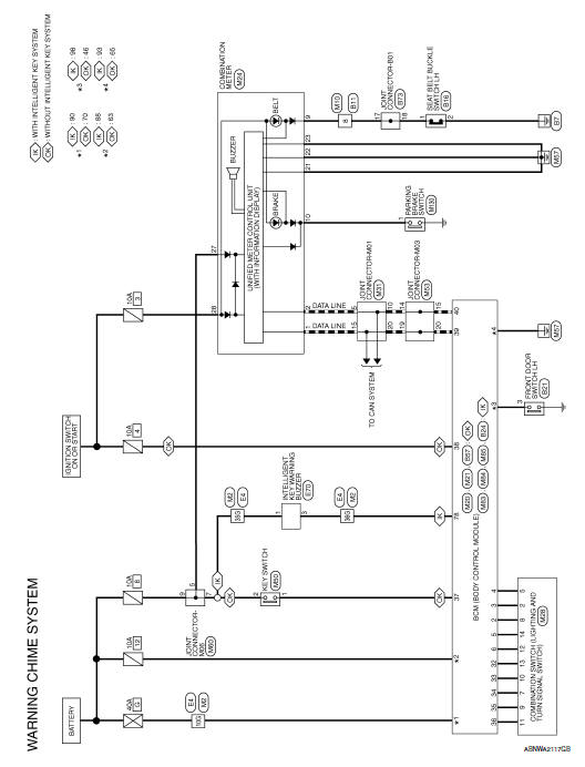
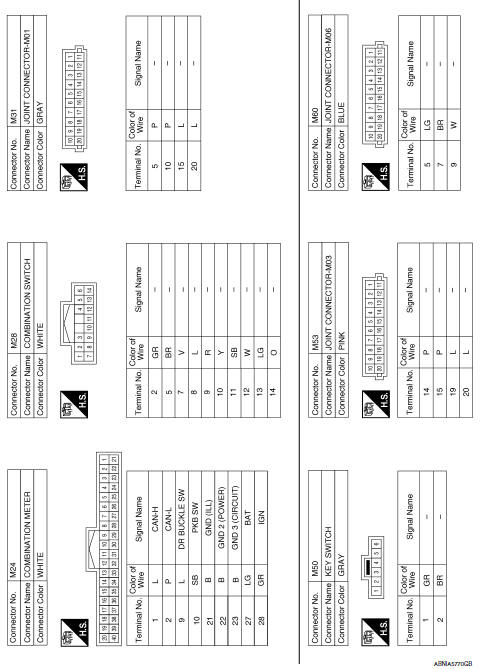
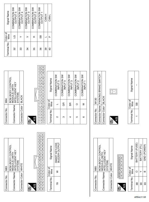
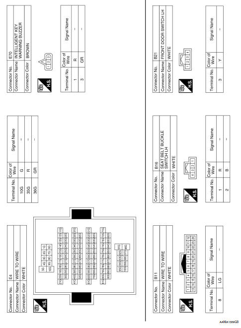
Warning chime system
Wiring diagram

 Ecu diagnosis information
Bcm, combination meter
List of ecu reference
...
 Basic inspection
Diagnosis and repair workflow
Work Flow
OVERALL SEQUENCE
DETAILED FLOW
1.OBTAIN INFORMATION ABOUT SYMPTOM
Interview the customer to obtain as much information as possible about the
conditio ...
Other materials:
Precaution
Precaution for supplemental restraint system (srs) "air bag" and "seat
belt pre-tensioner"
The supplemental restraint system such as “air bag” and “seat belt pre-tensioner”,
used along
with a front seat belt, helps to reduce the risk or severity of injur ...
Trip computer
When the ignition switch is placed in the ON
position, the modes of the trip
computer can be
selected by pressing the button on the
steering wheel. The following modes can be selected:
Trip A
Trip B
ECO Pedal Indicator
Instant fuel economy
Average fuel economy
Average speed
Dis ...
Wiring diagram
Remote keyless entry system
Wiring diagram
Power door lock system
Wiring Diagram
Trunk lid opener
Wiring diagram
...
